Photo Diary: Building the "Elektra I" Ultra-Low-Cost
Valveless Pulsejet, using ordinary hand tools and LESS THAN
FIVE DOLLARS worth of home improvement store materials
and a spark plug - PART I
by Larry Cottrill, Editor, jetZILLA Online Magazine
- All photos this page Copyright 2003 Larry Cottrill -
Table of Contents [Sections I-V below]:
I. Forming the combustion chamber [09 April 2004]
II. Welding the basic structure [10 April 2004]
III. Closing the chamber [13 April 2004]
IV. The fuel supply tube [16 April 2004]
V. Engine mounts [17 April 2004]
Table of Contents [Test Journal: Sections VI & higher go to Page 2]:
I. Forming the combustion chamber [09 April 2004]:
Next section Back to Contents Top of page To top of page 2
Subscribe to jetZILLA Online Magazine (it's FREE!)
Starting to enlarge the exhaust port knockout hole - here, I'm
using a large round file to quickly rough out the hole to the much
larger size needed [around 1.25 inches - a little larger than the
OD of the 1-inch conduit exhaust pipe material!]:
 A large half-round is needed, though, to really get the
hole smooth and uniformly round [as near a perfect circle
as you can make it]:
A large half-round is needed, though, to really get the
hole smooth and uniformly round [as near a perfect circle
as you can make it]:
 Creating the port for the intake stack - Make a punch mark in
the middle of the rounded corner. Then, start the hole with a
small, fast hand drill with a very small twist drill in the chuck
[3/32-inch diam. shown] and a few drops of light oil. Your twist
drill must be good and sharp to start without skidding off:
Creating the port for the intake stack - Make a punch mark in
the middle of the rounded corner. Then, start the hole with a
small, fast hand drill with a very small twist drill in the chuck
[3/32-inch diam. shown] and a few drops of light oil. Your twist
drill must be good and sharp to start without skidding off:
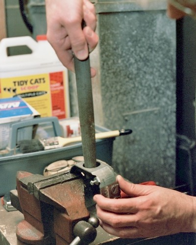
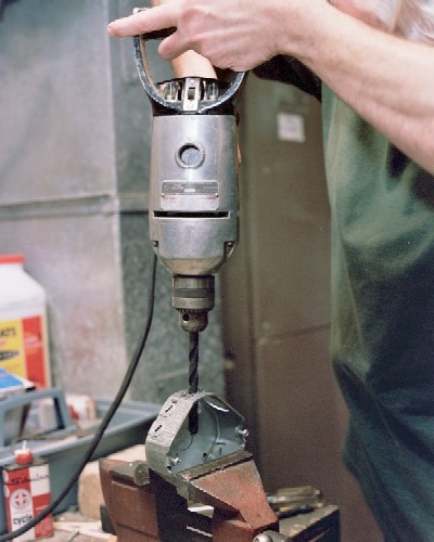
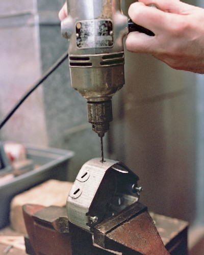 Re-drilling the stack port - Use the biggest drill you have, and make
sure the box is well anchored in the vise. Take it slow, and gradually work
through the steel, using added oil as needed. This is a 3/8-inch twist
drill in a big, slow 1/2HP gearhead drill:
Re-drilling the stack port - Use the biggest drill you have, and make
sure the box is well anchored in the vise. Take it slow, and gradually work
through the steel, using added oil as needed. This is a 3/8-inch twist
drill in a big, slow 1/2HP gearhead drill:
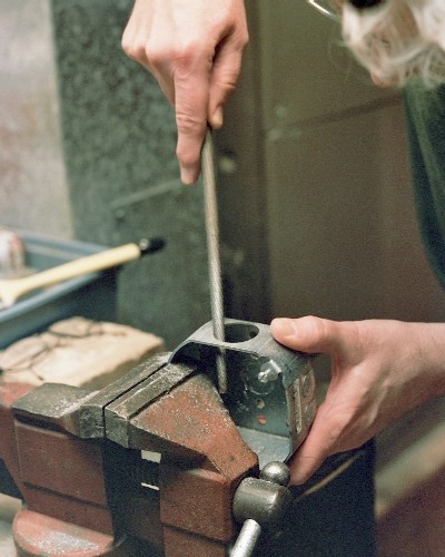
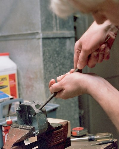
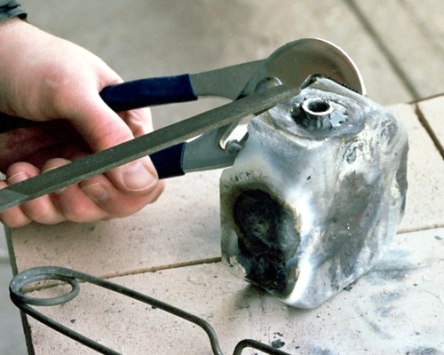
 Enlarging the intake stack port, using the full-round file. This
is a LOT of work, but it just needs to be big enough for the 3/4-inch
conduit to slip through. Then, re-work it at the top and bottom to
make it slightly elliptical, so the conduit will fit at the steeper
angle [about 60 degrees] shown in the drawing:
Enlarging the intake stack port, using the full-round file. This
is a LOT of work, but it just needs to be big enough for the 3/4-inch
conduit to slip through. Then, re-work it at the top and bottom to
make it slightly elliptical, so the conduit will fit at the steeper
angle [about 60 degrees] shown in the drawing:
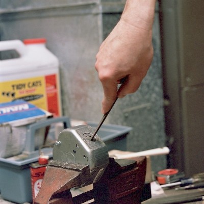
 Making the spark plug hole - since I planned to use a miniature plug,
I just used the two-drill technique once more to drill a 3/8-inch hole,
then enlarged it slightly with the full-round file. The drilling and
filing have to be done with great care, so the knockout won't be bent
out of shape. It will end up being welded into the box. [NOTE: If
you use a bigger plug, like a lawnmower plug, just remove the
knockout instead]:
Making the spark plug hole - since I planned to use a miniature plug,
I just used the two-drill technique once more to drill a 3/8-inch hole,
then enlarged it slightly with the full-round file. The drilling and
filing have to be done with great care, so the knockout won't be bent
out of shape. It will end up being welded into the box. [NOTE: If
you use a bigger plug, like a lawnmower plug, just remove the
knockout instead]:
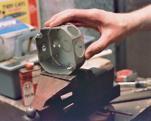
 After about an hour's work, here's the finished combustion chamber,
all ready for welding:
After about an hour's work, here's the finished combustion chamber,
all ready for welding:
 II. Welding the basic structure [10 April 2004]:
Previous section Next section Back to Contents Top of page To top of page 2
Subscribe to jetZILLA Online Magazine (it's FREE!)
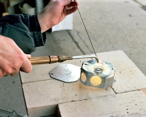
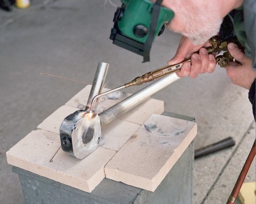
I started the welding by simply sealing up the knockouts in the
center of the cover plate and in the center of the wide face of
the box - only the slightest amount of filler rod is needed to
get started, then just work the puddle around the knockout:
II. Welding the basic structure [10 April 2004]:
Previous section Next section Back to Contents Top of page To top of page 2
Subscribe to jetZILLA Online Magazine (it's FREE!)
I started the welding by simply sealing up the knockouts in the
center of the cover plate and in the center of the wide face of
the box - only the slightest amount of filler rod is needed to
get started, then just work the puddle around the knockout:
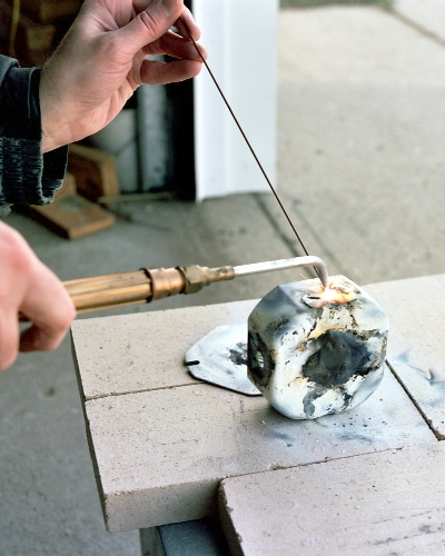
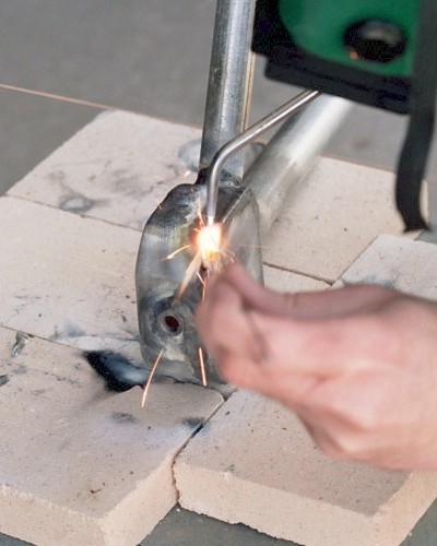
 The smaller 'Romex' knockouts are more difficult, because in this
case, there are some real gaps to be filled:
The smaller 'Romex' knockouts are more difficult, because in this
case, there are some real gaps to be filled:
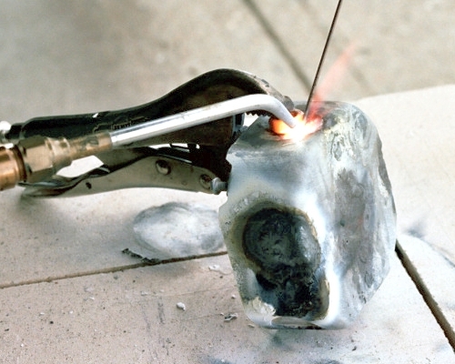
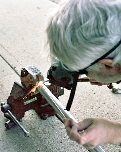
 After carefully welding the spark plug knockout to the box, the
spark plug nut is precisely aligned over the hole, and secured with
Vise Grips(TM) pliers while tying the nut down with a couple of
small tack welds:
After carefully welding the spark plug knockout to the box, the
spark plug nut is precisely aligned over the hole, and secured with
Vise Grips(TM) pliers while tying the nut down with a couple of
small tack welds:
 After tacking, remove the tool and work carefully around the nut
to get it fully welded in, using filler rod as required. Then,
file the top of the nut back to a smooth surface:
After tacking, remove the tool and work carefully around the nut
to get it fully welded in, using filler rod as required. Then,
file the top of the nut back to a smooth surface:
 Unfortunately, the threads will have to be cleaned up by running
a tap of the correct size through the nut.
Now, clamp the box in a vise and position the tailpipe [cut from
1-inch diameter rigid steel conduit] in place, and make a single
large tack weld, leaving about a 1/16-inch gap between the pipe
and the edge of the slightly oversize hole:
Unfortunately, the threads will have to be cleaned up by running
a tap of the correct size through the nut.
Now, clamp the box in a vise and position the tailpipe [cut from
1-inch diameter rigid steel conduit] in place, and make a single
large tack weld, leaving about a 1/16-inch gap between the pipe
and the edge of the slightly oversize hole:
 Then, carefully align the pipe with the chamber and make another
tack weld opposite the first one. Next, make two more at 90 degrees
from the first two, being careful to align the pipe as accurately
as possible!
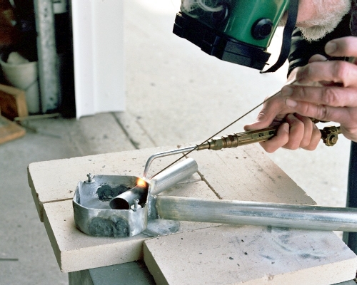
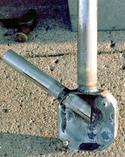
Looking through the chamber at the exhaust stack held in place
by the four tack welds [note the clearly visible space between the
chamber exhaust port and the pipe end]. The finished spark plug
mount is also clearly seen here, in the middle of the nearest wall
[i.e. the front end] of the chamber:
Then, carefully align the pipe with the chamber and make another
tack weld opposite the first one. Next, make two more at 90 degrees
from the first two, being careful to align the pipe as accurately
as possible!
Looking through the chamber at the exhaust stack held in place
by the four tack welds [note the clearly visible space between the
chamber exhaust port and the pipe end]. The finished spark plug
mount is also clearly seen here, in the middle of the nearest wall
[i.e. the front end] of the chamber:
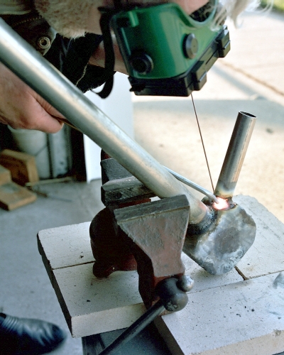
 After finishing the complete weld between the exhaust pipe and
the chamber, the intake stack is cut to size, carefully positioned
and tack welded in at one point only:
After finishing the complete weld between the exhaust pipe and
the chamber, the intake stack is cut to size, carefully positioned
and tack welded in at one point only:
 The stack is carefully aligned, and the angle checked to make sure
that the angled cutoff is accurately positioned. Then, after a couple
more tack welds and re-checking, it is welded solidly in place. It's
good to have the vise available for positioning the work so that the
entire joint is easy to reach:
The stack is carefully aligned, and the angle checked to make sure
that the angled cutoff is accurately positioned. Then, after a couple
more tack welds and re-checking, it is welded solidly in place. It's
good to have the vise available for positioning the work so that the
entire joint is easy to reach:
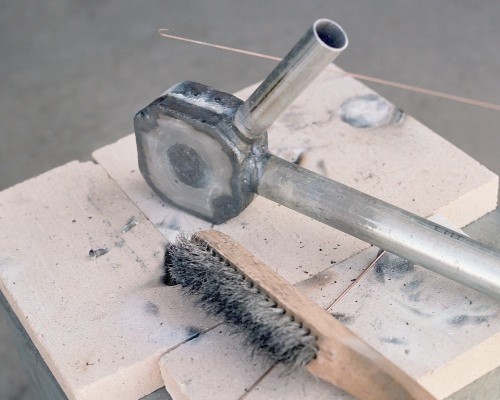
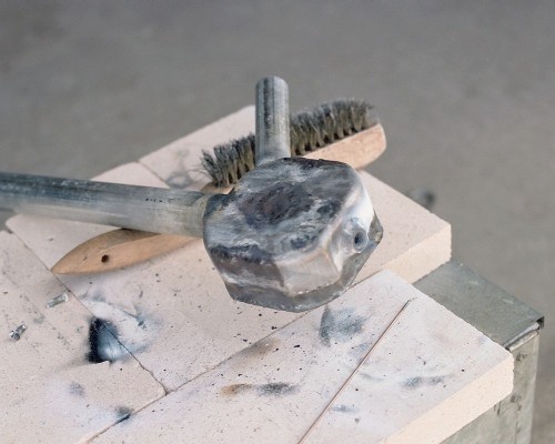
 The combustion chamber section of the Elektra I engine, all finished
except for welding on the side cover plate:
The combustion chamber section of the Elektra I engine, all finished
except for welding on the side cover plate:
 III. Closing the chamber [13 April 2004]:
Previous section Next section Back to Contents Top of page To top of page 2
Subscribe to jetZILLA Online Magazine (it's FREE!)
The cover plate is attached to the side of the chamber by means of
the two screws. Start the welding process by tack welding the cover
plate at points near the corners:
III. Closing the chamber [13 April 2004]:
Previous section Next section Back to Contents Top of page To top of page 2
Subscribe to jetZILLA Online Magazine (it's FREE!)
The cover plate is attached to the side of the chamber by means of
the two screws. Start the welding process by tack welding the cover
plate at points near the corners:
 Now, remove the two screws holding the plate to the box and finish
weld the edge of the cover plate down to the box wall, working from
tack weld to tack weld. There is enough overhang at the edge of the
coverplate to make almost the entire weld without filler rod -- the
rod is only needed when you get to the corner voids:
Now, remove the two screws holding the plate to the box and finish
weld the edge of the cover plate down to the box wall, working from
tack weld to tack weld. There is enough overhang at the edge of the
coverplate to make almost the entire weld without filler rod -- the
rod is only needed when you get to the corner voids:
 The finished combustion chamber section of the Elektra I engine, left side
rear and top view:
The finished combustion chamber section of the Elektra I engine, left side
rear and top view:
 The combustion chamber section of the Elektra I engine, right side front
and bottom view:
The combustion chamber section of the Elektra I engine, right side front
and bottom view:
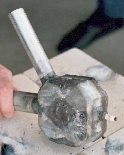
 The combustion chamber section of the Elektra I engine, closeup right
side view with spark plug threaded in, just to see how it looks:
The combustion chamber section of the Elektra I engine, closeup right
side view with spark plug threaded in, just to see how it looks:
 IV. The fuel supply tube [16 April 2004]:
Previous section Next section Back to Contents Top of page To top of page 2
Subscribe to jetZILLA Online Magazine (it's FREE!)
The original fuel supply tube is designed to drop into place and
be held by gravity alone. It is .125 inch OD copper tubing, with a
1/4-inch compression fitting bonded on with J-B Weld epoxy. It
slides loosely into a short section of .25 inch OD stainless tubing,
bonded inside the intake tube with J-B Weld. A notch in the near
side of the intake tube rim keeps it in alignment and prevents it
from vibrating out of place. This crude design allows for great
flexibility in experimenting with different fuel schemes:
IV. The fuel supply tube [16 April 2004]:
Previous section Next section Back to Contents Top of page To top of page 2
Subscribe to jetZILLA Online Magazine (it's FREE!)
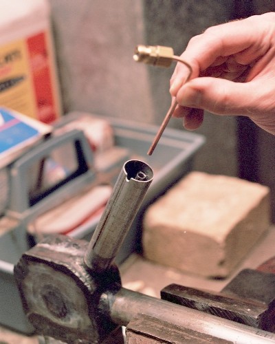
The original fuel supply tube is designed to drop into place and
be held by gravity alone. It is .125 inch OD copper tubing, with a
1/4-inch compression fitting bonded on with J-B Weld epoxy. It
slides loosely into a short section of .25 inch OD stainless tubing,
bonded inside the intake tube with J-B Weld. A notch in the near
side of the intake tube rim keeps it in alignment and prevents it
from vibrating out of place. This crude design allows for great
flexibility in experimenting with different fuel schemes:
 V. Engine mounts [17 April 2004]:
Previous section Next section Back to Contents Top of page To top of page 2
Subscribe to jetZILLA Online Magazine (it's FREE!)
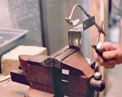
The two identical engine mounts are cut from a single hardware piece
called a 'fence rail bracket' - I used the jeweler's saw because it is
a favorite tool, but a hacksaw would have made quicker work of it [the
only other work needed before welding the mounts is to drill out the
holes to a larger size to fit the mounting bolts]:
V. Engine mounts [17 April 2004]:
Previous section Next section Back to Contents Top of page To top of page 2
Subscribe to jetZILLA Online Magazine (it's FREE!)
The two identical engine mounts are cut from a single hardware piece
called a 'fence rail bracket' - I used the jeweler's saw because it is
a favorite tool, but a hacksaw would have made quicker work of it [the
only other work needed before welding the mounts is to drill out the
holes to a larger size to fit the mounting bolts]:
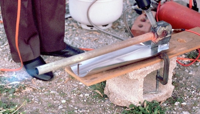
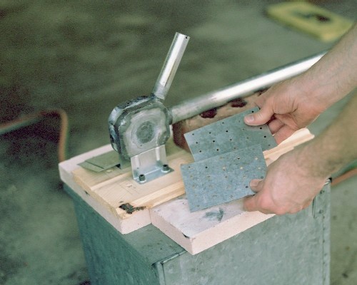
 Jigging the engine and mounts for tack welding - I used a scrap of flat
wood, though metal would be safer. To protect the wood from the torch
flame while tack welding, I covered as much as I could with the sheet
metal scraps shown. The engine itself is supported level by a brick
placed under the tailpipe:
Jigging the engine and mounts for tack welding - I used a scrap of flat
wood, though metal would be safer. To protect the wood from the torch
flame while tack welding, I covered as much as I could with the sheet
metal scraps shown. The engine itself is supported level by a brick
placed under the tailpipe:
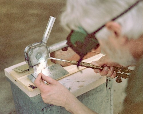
 Initial joining of the mounts to the engine, using just a couple of
small tack welds - the wood base got scorched in a couple of places;
if you use wood as I did, keep your fire extinguisher handy! After
the tack welding is done and the piece cools, unbolt it carefully
from the jig and do the finish welding, handling carefully so the
alignment isn't accidentally altered.
Initial joining of the mounts to the engine, using just a couple of
small tack welds - the wood base got scorched in a couple of places;
if you use wood as I did, keep your fire extinguisher handy! After
the tack welding is done and the piece cools, unbolt it carefully
from the jig and do the finish welding, handling carefully so the
alignment isn't accidentally altered.
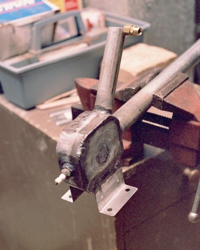
 After finish welding the mounts and attaching the fuel pipe and
spark plug, we get our first look at the finished Elektra I pulsejet
prototype:
After finish welding the mounts and attaching the fuel pipe and
spark plug, we get our first look at the finished Elektra I pulsejet
prototype:
 Previous section Next section Back to Contents Top of page To top of page 2
Subscribe to jetZILLA Online Magazine (it's FREE!)
Previous section Next section Back to Contents Top of page To top of page 2
Subscribe to jetZILLA Online Magazine (it's FREE!)
 All film processing and negative
scanning for this page was done by
Multi Media Imaging
1526 Walnut Street
Des Moines, Iowa USA 50309
515-309-3456
www.YourProLab.com
All film processing and negative
scanning for this page was done by
Multi Media Imaging
1526 Walnut Street
Des Moines, Iowa USA 50309
515-309-3456
www.YourProLab.com
|
|