S F O A - "Steel Floats On Air"
Main parts of the SFOA(TM) pulsejet engine

YOU could save
a child's life! >>>


The  S F O ATM  ball valve pulsejet project -
April 2002 - TODAY!
(last content update: 06 Apr 2004)

'SFOA' experimental ball valve pulsejet engine (c) 2004 Larry Cottrill
The original SFOA ball valve pulsejet engine


---   R E A D   T H I S   N O T I C E   ---
In viewing this site, YOU ARE AGREEING TO THE FOLLOWING TERMS AND CONDITIONS:
  1. PRODUCT DESIGNS SHOWN ON THIS PAGE ARE proposed embodiments of INVENTIONS OF LARRY B COTTRILL, and any or all rights may be assigned to Cottrill Cyclodyne Corporation (a for-profit corporation registered in the State of Iowa);
  2. PRODUCT DESIGNS SHOWN ON THIS PAGE ARE UNDER DEVELOPMENT AND THESE PRODUCTS AND THE UNDERLYING INVENTIONS potentially embodied in such products ARE NOT BEING MARKETED NOR OFFERED FOR SALE, pending completion of development efforts and possible patent application;
  3. NO ORDERS ARE BEING TAKEN for any future products shown or described herein, pending completion of development efforts and possible patent application for the underlying Inventions;
  4. NOTHING in the images or descriptions of proposed future products on this page SHALL BE CONSTRUED TO LIMIT the range of embodied applications for the underlying Inventions, NOR IN ANY WAY TO WARRANT SUCH INVENTIONS or any derivative embodiments as to fitness FOR ANY PARTICULAR PURPOSE;
  5. In showing product information on this page, NO CLAIMS OF ANY KIND ARE MADE in regard to performance, manufacturability, marketability, product safety, or fitness for any particular purpose;
  6. In showing product information on this page, NO LICENSE IS GRANTED to duplicate, re-scale, publish, revise or offer these designs to third parties on any basis;
  7. PUBLIC PRESENTATION OF THIS PAGE and the images and descriptions of these proposed future products SHALL NOT CONSTITUTE ANY WAIVER OF PATENT RIGHTS OR OTHER RIGHTS the Inventor or any licensee or assign thereof may have in relation to these Inventions, nor does such presentation constitute public disclosure of the Inventions, nor permit public disclosure of the underlying Inventions in any manner;
  8. BY VIEWING THIS PAGE, YOU AGREE THAT YOU UNDERSTAND THAT THE BUILDING AND TESTING OF JET ENGINES IS INHERENTLY DANGEROUS TO PROPERTY, LIFE AND LIMB, AND THAT THE DESIGNS SHOWN ARE NOT REPRESENTED AS EXPERIMENTALLY PROVEN DESIGNS;
  9. AND YOU FURTHER AGREE THAT ANY ATTEMPT on your part TO BUILD, manufacture, test, modify and/or utilize an actual embodiment of the design(s) shown CONSTITUTES UNAUTHORIZED DUPLICATION, THAT YOU ARE BUILDING AND TESTING THE DESIGN(S) AT YOUR OWN RISK, AND THAT YOU ARE ASSUMING TOTAL LEGAL RESPONSIBILITY FOR ALL DAMAGES OF EVERY KIND THAT MAY BE INCURRED in such building, manufacturing, testing, modifying and/or utilizing them for any purpose whatsoever; AND THAT YOU AGREE TO HOLD THE DESIGNER AND COTTRILL CYCLODYNE CORPORATION COMPLETELY HARMLESS IN REGARD TO ANY SUCH DAMAGES YOU INCUR, WITHOUT LIMITATION.


Pulsodyne SFOATM pulsejet engine design and construction:
by Larry Cottrill, Director of Product Development

Here is the ball valve engine as I originally proposed to members of Kenneth Moller's Pulsejet Forum in late March, 2002. The idea is that a hardened and plated steel ball (erroneously labeled 'Ball bearing' in this drawing) lying loosely in a hexagonal tunnel can be forced back and forth against and away from a conical valve seat by the cyclical pressure changes (from explosion to suction), thus acting as the pulsejet valve. This is only possible if the ball is very small, so that the mass-to-surface-area ratio is quite low. Therefore, this valve design is only usable for the very smallest possible pulsejet engine sizes -- exactly where my greatest pulsejet interest lies.

The front end is adjustable by threading it in and out of the combustion chamber, thus allowing the total travel of the ball to be adjusted for experimentation. A transverse steel rod would be mounted in the chamber to act as the rear valve stop:

This is the final version posted on the Pulsejet Forum, about a month later. The only real change is to the valve stop mechanism -- after procuring actual set screws of appropriate size, I found that the hexagonal "Allen" socket is pre-formed somewhat deeper than the largest ball that will slide into it, thus preventing the transverse rod from being useful as a stop for the rear travel of the ball. Also, I felt from my prior experience with very small pulsejet testing that a "bluff body" of some sort was probably necessary to diffuse and slow the intake air flow -- like a crude flameholder. So, I came up with the idea of using a second ball, welded to a folded steel washer which would in turn be welded into the ignition chamber right behind the threaded insert:


Pulsodyne SFOATM pulsejet engine project photos:
by Larry Cottrill
This photo shows the SFOA engine raw materials lined up right beside the lathe-finished ready-to-weld pieces. Raw materials (back row from left to right) are: 12 gram CO2 cylinder (nose cut & filed as shown to fit point of set screw), 5/8-18 set screw, 5/8-18 hex nut, CO2 cylinder, and 3/8 in. (nom.) galvanized steel pipe (12 inch length). Finished pieces (front row, left to right): intake body (set screw welded to cylinder neck end, drilled out and faced), 9/32 inch steel ball valve body, 5/8-18 lock ring (turned from hex nut), 5/8-18 threaded sleeve (turned from same nut), folded-washer-and-ball valve stop/bluff body, ignition chamber (turned from CO2 cylinder) and tailpipe (turned from pipe). NOTE: In reality, only one CO2 cylinder is needed to form both the intake bell and the ignition chamber; the extra cylinder shown at the front end is an attempt to more clearly illustrate the development of raw steel to finished pieces. The CO2 cylinders are 3/4 inch (approx. 19mm) OD.

This detail shot shows the aft end of the intake body with the 9/32 inch steel ball resting in place inside its hexagonal track, the lock ring (the ring with hand-filed notches in the outer rim), the threaded insert and the ignition chamber front end into which the insert will be welded.

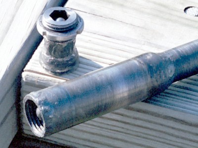
The aft end of the ignition chamber (turned out to fit the tailpipe) and the front end of the tailpipe (note slight 'shelf' turned around the front edge). Made in this way, the pipe 'sockets' into the chamber rear aperture slightly, but cannot slide through into the interior -- the fit is essentially self-aligning. The finished pipe wall thickness is approx. 1/16 inch (1.5mm); the pipe ID is approx. 1/2 inch (13mm).

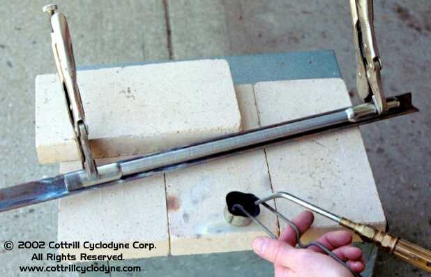
This shot shows how the tailpipe and ignition chamber are jigged for welding. A straight piece of small steel angle is used. First, a spare CO2 cylinder (must be perfectly identical to the raw cylinder used for the chamber) is clamped in place at the right end. The aft end of the pipe is placed on the cylinder neck. Finally, at the left, the aft end of the chamber is slid onto the specially turned front end of the pipe, and clamped -- the pipe is held in perfect alignment between the two cylinders. A couple of tack welds will be made between chamber and pipe; then, the clamp on the chamber will be loosened and the assembly rolled 180 degrees and re-clamped as before, and a couple more tack welds will be made. Finish welding can then be done with the assembly removed from the jig, with the tack welds preserving the alignment while welding.

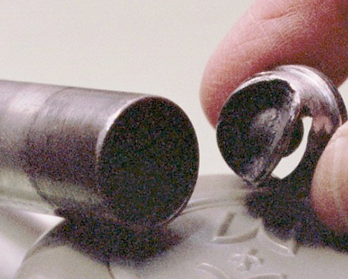
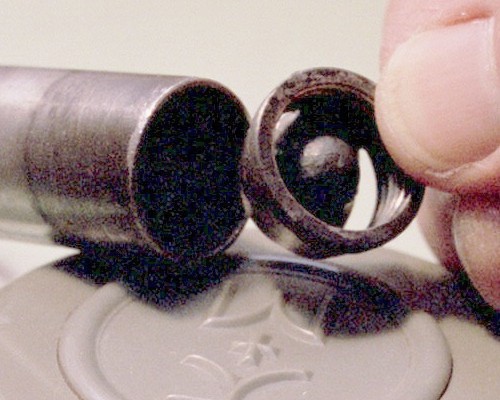
These two shots show the tail end and front end of the fully-welded sleeve and stop ball assembly, ready to slip into the front of the chamber, which appears at the left in both photos. Note in the top photo how the side weld has been smoothed off by filing to allow the sleeve to slide easily into the chamber wall. [Compare this to the geometry shown in the second drawing at the top of the page.]
Photos Copyright 2003 Cottrill Cyclodyne Corporation

The finished state of the front end of the chamber, with the ball stop and flameholder assembly fitted into the chamber and welded into place, is shown in this photo. The valve ball can be seen resting in the hexagonal channel in the rear of the intake body.
Photo Copyright 2003 Cottrill Cyclodyne Corporation

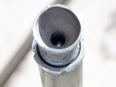
A "fully assembled" view looking into the front end of the intake body, which has been threaded in and locked with the lock ring. The valve body is run in until the ball has just a few thousandths of an inch of free play between its seat and the stop behind it -- the exact setting for good operation will need to be determined experimentally. The steel valve ball is just visible as a tiny reflection of blue sky at the far end of the venturi throat in this photo.
Photo Copyright 2003 Cottrill Cyclodyne Corporation


SPECIAL THANKS to my friend (and brilliant artist!) Jim Russell (Jim Russell Design, Des Moines, Iowa, USA), for graciously allowing me to use his turning lathe to generate the parts shown. His assistance was invaluable, especially since this was the first time I had touched a metal-turning lathe in about thirty-five years!


Multi Media Imaging, Des Moines, IA
All film processing and negative 
scanning for this page was done by

          Multi Media Imaging
          1526 Walnut Street
          Des Moines, Iowa  USA  50309
          515-309-3456
          www.multi-media-inc.com

"To God Alone be the Glory"
- Johann Sebastian Bach 1685 - 1750


The Pulsodyne SFOATM miniature aviation powerplant
         - now under development by

Corporate Main Office
11905 NE 110th Ave
Mingo,    IA 50168-9500

Contact:
  SFOA@cottrillcyclodyne.com

Page updated: 08 April 2004

Copyright 2004 Cottrill Cyclodyne Corporation
- All rights reserved -