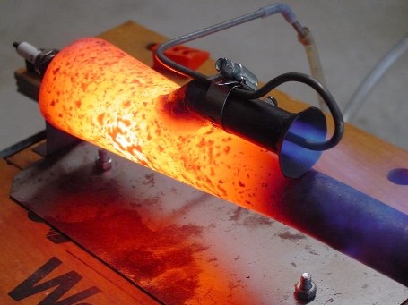
Photo Diary: Building and running 'The Short Lady'
Focused Wave Valveless Pulsejet Engine
by Larry Cottrill, Editor, jetZILLA Online Magazine
- All photos Copyright 2004 Steve Bukowsky and Larry Cottrill -
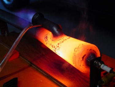
 Steve Bukowsky's original 'Short Lady' build, in good lean running
on propane vapor fuel - exhaust ejection from the rear-facing intake
can be clearly seen in this photo. This shows Steve's final method
of supplying fuel vapor straight down the center of the intake.
Steve's 'Short Lady' started and ran on the very first try!
Photo Copyright 2004 Steve Bukowsky
I. Getting started - "parts is parts":
Next section Back to Contents Top of page To top of page 2
Subscribe to jetZILLA Online Magazine (it's FREE!)
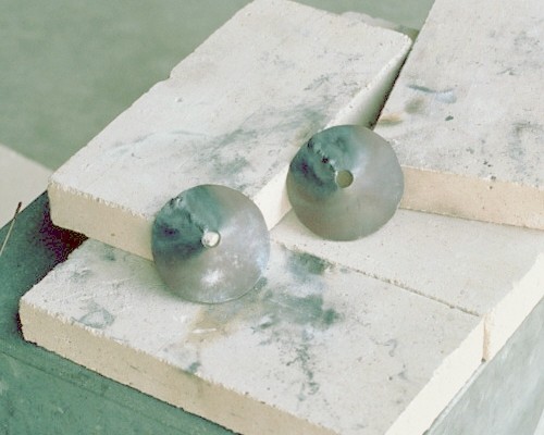
Not having an equipped shop, I had no good way of rolling the
combustion chamber wall and end cones myself. Since Steve had
obviously done such a nice job making these in his school shop,
I negotiated with him to make two sets of cones for me, at a
very reasonable price. Here is Steve's shot of the combustion
chamber parts as he was working on them for me, alonside his
finished 'Short Lady' engine. Note that the wall cones are fully
formed and tack welded in this shot; the front end cones [which
I call "domes"] are cut but not yet rolled and tacked:
Steve Bukowsky's original 'Short Lady' build, in good lean running
on propane vapor fuel - exhaust ejection from the rear-facing intake
can be clearly seen in this photo. This shows Steve's final method
of supplying fuel vapor straight down the center of the intake.
Steve's 'Short Lady' started and ran on the very first try!
Photo Copyright 2004 Steve Bukowsky
I. Getting started - "parts is parts":
Next section Back to Contents Top of page To top of page 2
Subscribe to jetZILLA Online Magazine (it's FREE!)
Not having an equipped shop, I had no good way of rolling the
combustion chamber wall and end cones myself. Since Steve had
obviously done such a nice job making these in his school shop,
I negotiated with him to make two sets of cones for me, at a
very reasonable price. Here is Steve's shot of the combustion
chamber parts as he was working on them for me, alonside his
finished 'Short Lady' engine. Note that the wall cones are fully
formed and tack welded in this shot; the front end cones [which
I call "domes"] are cut but not yet rolled and tacked:
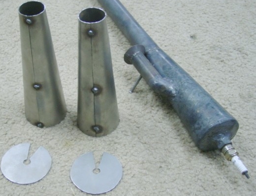 Photo Copyright 2004 Steve Bukowsky
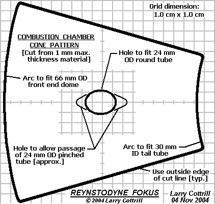
If you have a way of smoothly rolling your own cones, you can
print these graphics and scale them up so the squares form a
1 cm grid, then cut out the patterns to make your own cones
out of 1 mm sheet steel. If you want, you can make the hole
for the intake after rolling and welding the main cone, but
you can still use the pattern to locate the hole accurately.
If you want to use a pinched intake pipe [recommended], use
the longer, diamond-shaped hole outline. Important: You
should use the outside edge of each heavy black outline
as your cut line.
Main Combustion Chamber Cone Pattern
Photo Copyright 2004 Steve Bukowsky
If you have a way of smoothly rolling your own cones, you can
print these graphics and scale them up so the squares form a
1 cm grid, then cut out the patterns to make your own cones
out of 1 mm sheet steel. If you want, you can make the hole
for the intake after rolling and welding the main cone, but
you can still use the pattern to locate the hole accurately.
If you want to use a pinched intake pipe [recommended], use
the longer, diamond-shaped hole outline. Important: You
should use the outside edge of each heavy black outline
as your cut line.
Main Combustion Chamber Cone Pattern
 Scalable pattern for the combustion chamber cone - Copyright 2004 Larry Cottrill
Combustion Chamber Dome Pattern
Scalable pattern for the combustion chamber cone - Copyright 2004 Larry Cottrill
Combustion Chamber Dome Pattern
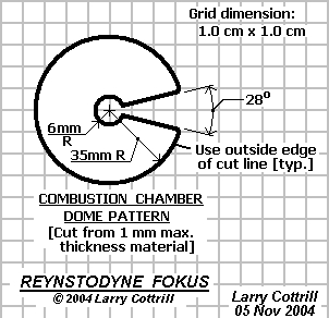 Scalable pattern for the combustion chamber dome - Copyright 2004 Larry Cottrill
II. Preliminary welding:
Previous section Next section Back to Contents Top of page To top of page 2
Subscribe to jetZILLA Online Magazine (it's FREE!)
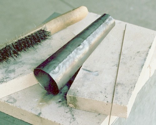
The combustion chamber wall cone side seam was welded in several
passes, to minimize distortion. The three tack welds were blended
in, but left pretty good sized lumps; I simply dressed them down
later on, using a flat file. Both cones I prepared looked just fine, but
were slightly out of round from welding. This was easily corrected
by careful squeezing in the bench vise later:
Scalable pattern for the combustion chamber dome - Copyright 2004 Larry Cottrill
II. Preliminary welding:
Previous section Next section Back to Contents Top of page To top of page 2
Subscribe to jetZILLA Online Magazine (it's FREE!)
The combustion chamber wall cone side seam was welded in several
passes, to minimize distortion. The three tack welds were blended
in, but left pretty good sized lumps; I simply dressed them down
later on, using a flat file. Both cones I prepared looked just fine, but
were slightly out of round from welding. This was easily corrected
by careful squeezing in the bench vise later:
 Similarly, the front end dome seams were quickly finish welded:
 III. Spark plug mount:
Previous section Next section Back to Contents Top of page To top of page 2
Subscribe to jetZILLA Online Magazine (it's FREE!)
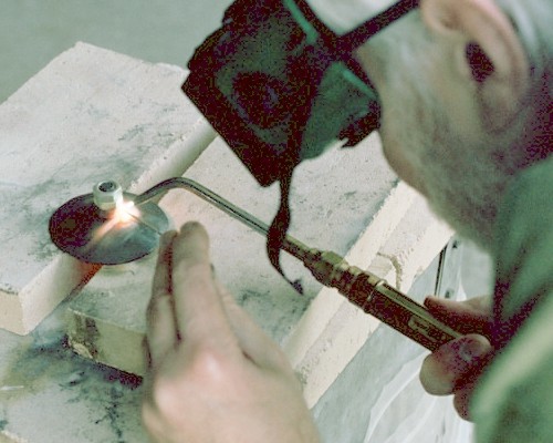
Here's a shot of spark plug mount welding technique. The center
hole in the dome was filed out just enough for a 3/8-24 bolt to go
through from behind, and a nut tightened on. Two more nuts [which
appear white in the photo] are threaded finger tight on top of that,
to protect the bolt threads from the torch heat. This weld takes a
fair amount of heat and filler rod, and you have to be careful not to
slop any weld metal onto the outer nuts, so they can be removed
easily afterward:
III. Spark plug mount:
Previous section Next section Back to Contents Top of page To top of page 2
Subscribe to jetZILLA Online Magazine (it's FREE!)
Here's a shot of spark plug mount welding technique. The center
hole in the dome was filed out just enough for a 3/8-24 bolt to go
through from behind, and a nut tightened on. Two more nuts [which
appear white in the photo] are threaded finger tight on top of that,
to protect the bolt threads from the torch heat. This weld takes a
fair amount of heat and filler rod, and you have to be careful not to
slop any weld metal onto the outer nuts, so they can be removed
easily afterward:
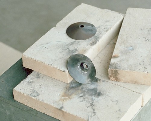
 After cooling, I applied penetrating oil and loosened the nuts.
Removing the outer nuts was easy, but the bolt had to be extracted
from the welded nut using a box-end wrench from behind while
gently gripping the dome in the bench vise. Here's the finished
product, with the second dome in the background, waiting to be
done in the same way:
After cooling, I applied penetrating oil and loosened the nuts.
Removing the outer nuts was easy, but the bolt had to be extracted
from the welded nut using a box-end wrench from behind while
gently gripping the dome in the bench vise. Here's the finished
product, with the second dome in the background, waiting to be
done in the same way:
 IV. Welding on the tailpipe tube:
Previous section Next section Back to Contents Top of page To top of page 2
Subscribe to jetZILLA Online Magazine (it's FREE!)
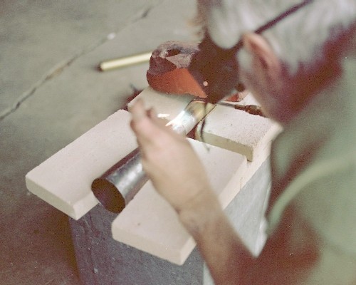
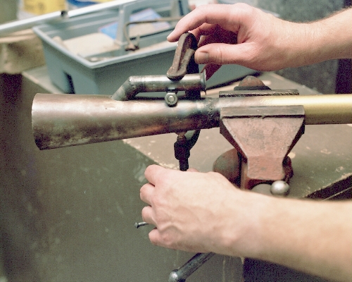
Next, the tailpipe tube was cut from a piece of TV antenna mast
tubing. I found that for a perfect fit between the combustion
chamber cone and the tailpipe tube, the front end of the tube had
to be expanded a fraction of an inch. This was done by heating
and gentle nudging all around with a small ball peen hammer until
it was a near-perfect fit. Then, I set up a careful 'temporary jig'
of firebrick to hold the pieces in alignment for tack welding.
Proper alignment was established by sighting down the tube from
the rear and adjusting as needed during tack welding. Finally, the
finish weld was run around the seam in four passes, concentrating
on using a minimum of filler rod to try to keep the inside
surface as smooth as possible. Here's a shot of the tack welding
operation, showing the firebrick 'jigging' - note the plain brick
at the rear, pinning the tailpipe to hold it steady:
IV. Welding on the tailpipe tube:
Previous section Next section Back to Contents Top of page To top of page 2
Subscribe to jetZILLA Online Magazine (it's FREE!)
Next, the tailpipe tube was cut from a piece of TV antenna mast
tubing. I found that for a perfect fit between the combustion
chamber cone and the tailpipe tube, the front end of the tube had
to be expanded a fraction of an inch. This was done by heating
and gentle nudging all around with a small ball peen hammer until
it was a near-perfect fit. Then, I set up a careful 'temporary jig'
of firebrick to hold the pieces in alignment for tack welding.
Proper alignment was established by sighting down the tube from
the rear and adjusting as needed during tack welding. Finally, the
finish weld was run around the seam in four passes, concentrating
on using a minimum of filler rod to try to keep the inside
surface as smooth as possible. Here's a shot of the tack welding
operation, showing the firebrick 'jigging' - note the plain brick
at the rear, pinning the tailpipe to hold it steady:
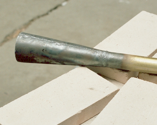
 The finish weld is reasonably reinforced, smooth inside, and
holds the chamber in near-perfect alignment with the tube
[smoothness is critical here; a slight error in alignment is of
no consequence]:
The finish weld is reasonably reinforced, smooth inside, and
holds the chamber in near-perfect alignment with the tube
[smoothness is critical here; a slight error in alignment is of
no consequence]:
 V. Fitting and welding in the intake tube:
Previous section Next section Back to Contents Top of page To top of page 2
Subscribe to jetZILLA Online Magazine (it's FREE!)
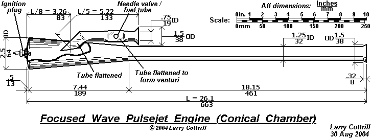
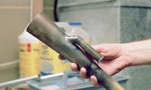
Steve followed my design exactly, using 3/4-inch EMT [rigid
electrical conduit] to built his intake tube and flattening the
lower end slightly. The hole in the chamber has to be placed as
accurately as possible to the design location shown on the
drawing. Note that Steve chose to fit his intake as practically
the last step in building his engine - note, too, the beautiful
intake flare hand-formed from sheet metal and welded onto the
outer end of the tube:
V. Fitting and welding in the intake tube:
Previous section Next section Back to Contents Top of page To top of page 2
Subscribe to jetZILLA Online Magazine (it's FREE!)
Steve followed my design exactly, using 3/4-inch EMT [rigid
electrical conduit] to built his intake tube and flattening the
lower end slightly. The hole in the chamber has to be placed as
accurately as possible to the design location shown on the
drawing. Note that Steve chose to fit his intake as practically
the last step in building his engine - note, too, the beautiful
intake flare hand-formed from sheet metal and welded onto the
outer end of the tube:
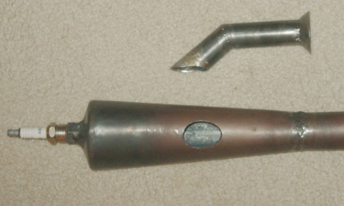 Photo Copyright 2004 Steve Bukowsky
Based on Steve's experience running his build of this engine,
I felt I could try reducing the intake to 5/8-inch EMT. Also,
I decided to leave the tube round over its whole length because
of this smaller internal diameter. I formed my flare just by
heating and hammering, and mine is not as smoothly formed as
Steve's finely crafted example. The hole is formed by drilling and
then hand finishing with large and small round files, trying to get
the most precise location and fit possible:
Photo Copyright 2004 Steve Bukowsky
Based on Steve's experience running his build of this engine,
I felt I could try reducing the intake to 5/8-inch EMT. Also,
I decided to leave the tube round over its whole length because
of this smaller internal diameter. I formed my flare just by
heating and hammering, and mine is not as smoothly formed as
Steve's finely crafted example. The hole is formed by drilling and
then hand finishing with large and small round files, trying to get
the most precise location and fit possible:
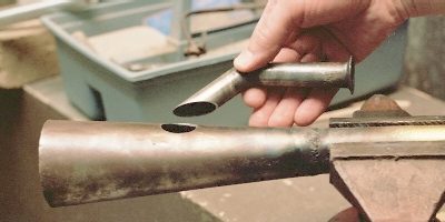 I wanted to mount the intake tube before welding on the front
dome so that it would be possible to visually inspect the lower
end of the tube for perfect alignment in the middle of the chamber.
I jigged the intake for tack welding by using a 5/16-inch bolt and
nut and an old C-clamp, set just tight enough to hold it:
I wanted to mount the intake tube before welding on the front
dome so that it would be possible to visually inspect the lower
end of the tube for perfect alignment in the middle of the chamber.
I jigged the intake for tack welding by using a 5/16-inch bolt and
nut and an old C-clamp, set just tight enough to hold it:
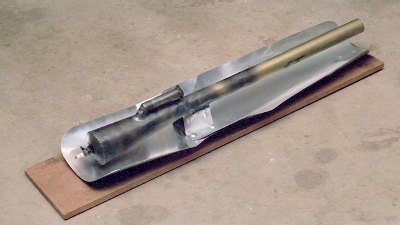
 The end result - the intake tube, finish welded into the chamber wall:
 Previous section Next section Back to Contents Top of page To top of page 2
Subscribe to jetZILLA Online Magazine (it's FREE!)
Previous section Next section Back to Contents Top of page To top of page 2
Subscribe to jetZILLA Online Magazine (it's FREE!)
 All film processing and negative
scanning for Larry's shots was done by
Multi Media Imaging
1526 Walnut Street
Des Moines, Iowa USA 50309
515-309-3456
www.multi-media-inc.com
All film processing and negative
scanning for Larry's shots was done by
Multi Media Imaging
1526 Walnut Street
Des Moines, Iowa USA 50309
515-309-3456
www.multi-media-inc.com
|
|