Photo Diary: Building and running 'The Short Lady'
Focused Wave Valveless Pulsejet Engine (cont'd)
by Larry Cottrill, Editor, jetZILLA Online Magazine
- All photos Copyright 2004 Steve Bukowsky and Larry Cottrill -
VI. Engine mount blades:
Previous section Next section Back to Contents Top of page To top of page 1
Subscribe to jetZILLA Online Magazine (it's FREE!)
The two identical engine mounts are cut from a single hardware piece
called a 'fence rail bracket' - I used the jeweler's saw because it is
a favorite tool, but a hacksaw would have made quicker work of it. The
only other work needed before welding the mounts is to drill out the
holes to a larger size to fit the 1/4-inch mounting bolts:
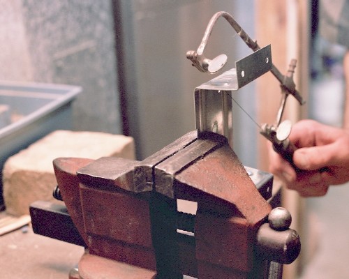 To weld the mounts, they need to be temporarily bolted down to a flat
piece of metal through properly spaced holes, then bent inward to meet
the underside of the tailpipe, and tack welded in place [the mounts
are located right under the balance point of the engine]. Then, unbolt
them and finish weld onto the tailpipe. Do not skimp on these welds -
they have to carry the entire thrust force of your engine! [These welds
can be seen in the closeup of the finished engine front end, below.]
VII. Welding on the front end dome:
Previous section Next section Back to Contents Top of page To top of page 1
Subscribe to jetZILLA Online Magazine (it's FREE!)
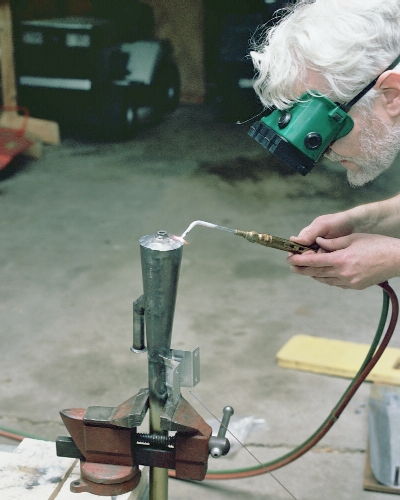
The final weld of the entire project - getting the front dome welded
on, mostly by just melting the edges together, as shown here. You
start out by mounting the engine as near vertical as possible in the
vise, center the dome on the top end of the chamber and do 4-6 tack
welds, using just a bit of filler rod [you might want a small weight
resting on the plug mount to hold it during tacking]. Then, work your
way around from tack to tack, melting the dome edge into the front
chamber wall edge, using filler rod only where significant gaps are
encountered:
To weld the mounts, they need to be temporarily bolted down to a flat
piece of metal through properly spaced holes, then bent inward to meet
the underside of the tailpipe, and tack welded in place [the mounts
are located right under the balance point of the engine]. Then, unbolt
them and finish weld onto the tailpipe. Do not skimp on these welds -
they have to carry the entire thrust force of your engine! [These welds
can be seen in the closeup of the finished engine front end, below.]
VII. Welding on the front end dome:
Previous section Next section Back to Contents Top of page To top of page 1
Subscribe to jetZILLA Online Magazine (it's FREE!)
The final weld of the entire project - getting the front dome welded
on, mostly by just melting the edges together, as shown here. You
start out by mounting the engine as near vertical as possible in the
vise, center the dome on the top end of the chamber and do 4-6 tack
welds, using just a bit of filler rod [you might want a small weight
resting on the plug mount to hold it during tacking]. Then, work your
way around from tack to tack, melting the dome edge into the front
chamber wall edge, using filler rod only where significant gaps are
encountered:
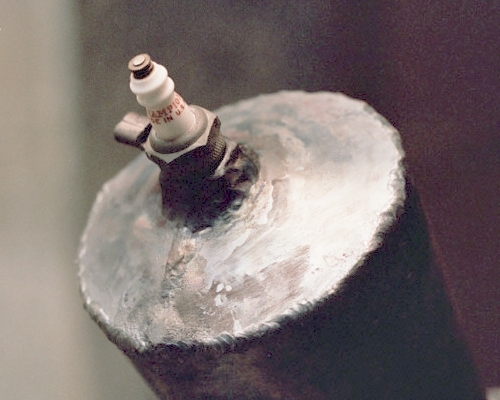
 The finish welded front end of the chamber, seen here with the
spark plug temporarily threaded into place:
The finish welded front end of the chamber, seen here with the
spark plug temporarily threaded into place:
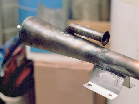
 Closeup of the finished front end, seen from the left rear. In
this view, the cone-to-tailpipe weld and engine mount weld are
clearly seen:
Closeup of the finished front end, seen from the left rear. In
this view, the cone-to-tailpipe weld and engine mount weld are
clearly seen:
 VIII. Static testing - starting and running with propane
Previous section Next section Back to Contents Top of page To top of page 1
Subscribe to jetZILLA Online Magazine (it's FREE!)
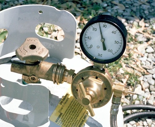
For testing, propane is perhaps the easiest fuel to use, and in
most areas, the most readily available. To use it successfully, you
need a good low-pressure high-flow regulator. You should be able to
get a propane regulator designed for cutting torches at any good
welding shop. You won't need the 26 PSI shown in this photo - just
10 or 15 PSI will work nicely. The photo shows, from left to right,
the propane tank valve, the regulator and low pressure gauge [the
regulator goes into the valve via a left-hand thread], and the
needle valve and delivery hose [the little tee-handle of the needle
valve, in a near-vertical orientation, is just barely visible
against the background]:
VIII. Static testing - starting and running with propane
Previous section Next section Back to Contents Top of page To top of page 1
Subscribe to jetZILLA Online Magazine (it's FREE!)
For testing, propane is perhaps the easiest fuel to use, and in
most areas, the most readily available. To use it successfully, you
need a good low-pressure high-flow regulator. You should be able to
get a propane regulator designed for cutting torches at any good
welding shop. You won't need the 26 PSI shown in this photo - just
10 or 15 PSI will work nicely. The photo shows, from left to right,
the propane tank valve, the regulator and low pressure gauge [the
regulator goes into the valve via a left-hand thread], and the
needle valve and delivery hose [the little tee-handle of the needle
valve, in a near-vertical orientation, is just barely visible
against the background]:
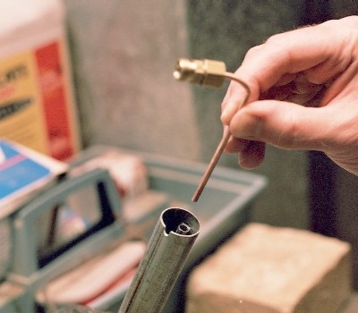
 The fuel pipe used in the engine intake for testing is just a
simple 1/8-inch OD copper tube with a hose fitting, bent to reach
into the intake. Here's the fuel pipe I used [shown with an earlier
experimental engine, the Elektra I]. The tube reaches about three
inches down into the intake tube. The pipe can be soldered to the
hose fitting or cemented with fireplace cement - just be sure the
passage of fuel from the hose into the pipe is clear, and there
are no leaks between the pipe and the fitting. This fitting must be
chosen to perfectly match the fittings on the hose ends.
The fuel pipe used in the engine intake for testing is just a
simple 1/8-inch OD copper tube with a hose fitting, bent to reach
into the intake. Here's the fuel pipe I used [shown with an earlier
experimental engine, the Elektra I]. The tube reaches about three
inches down into the intake tube. The pipe can be soldered to the
hose fitting or cemented with fireplace cement - just be sure the
passage of fuel from the hose into the pipe is clear, and there
are no leaks between the pipe and the fitting. This fitting must be
chosen to perfectly match the fittings on the hose ends.
 Important Note: When you set up the fuel pipe in your engine for
testing, you will need to protect the first 10-12 inches of hose
from the engine heat. You can do this by wrapping the hose and
attached fitting with crumpled aluminum foil.
A couple of other things needed for starting are a high-voltage
spark ignition system and an air blower. The blower can be a leaf
blower or a shop vacuum with a 'crevice tool' nozzle and the hose
set up for blowing air. The ignition system I use is an old 'Model
T Ford' spark coil run from a 12-volt battery and equipped with a
long pair of spark plug wires with 'crocodile clips' at the ends.
There are more modern alternatives - anything will work that can
deliver a low-current continuous spark of 5,000 volts or higher.
It needs to be equipped with a simple on/off switch to the
battery. The 'hot' clip goes to the top terminal of the spark plug
and the 'ground' can be attached to an engine mount as far from
the engine body as possible [or even to the aluminum heat shield,
if provided and in good electrical contact with the engine].
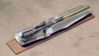
The simplest test mount is probably a flat wood plank, about
3/4 inch thick and about 6 inches wide, and a little longer than
the engine. With wood, heat shielding is essential! The best heat
shielding material is sheet aluminum, which is light, cheap and
very easy to work with. I made mine in two pieces, cutting them
from 'dryer duct' with large scissors, then drilling them out in
four places so the engine mount bolts would go down through them
when the engine is bolted on. A single long piece of aluminum duct
would have been just as good. The bolts I used are short, large
head 1/4-inch aluminum bolts; 1/4-20 'tee nuts' are driven into
the holes from the bottom side of the board. The result is an
engine and test mount assembly that can be easily handled as a
unit which can be clamped to any convenient heavy object:
Important Note: When you set up the fuel pipe in your engine for
testing, you will need to protect the first 10-12 inches of hose
from the engine heat. You can do this by wrapping the hose and
attached fitting with crumpled aluminum foil.
A couple of other things needed for starting are a high-voltage
spark ignition system and an air blower. The blower can be a leaf
blower or a shop vacuum with a 'crevice tool' nozzle and the hose
set up for blowing air. The ignition system I use is an old 'Model
T Ford' spark coil run from a 12-volt battery and equipped with a
long pair of spark plug wires with 'crocodile clips' at the ends.
There are more modern alternatives - anything will work that can
deliver a low-current continuous spark of 5,000 volts or higher.
It needs to be equipped with a simple on/off switch to the
battery. The 'hot' clip goes to the top terminal of the spark plug
and the 'ground' can be attached to an engine mount as far from
the engine body as possible [or even to the aluminum heat shield,
if provided and in good electrical contact with the engine].
The simplest test mount is probably a flat wood plank, about
3/4 inch thick and about 6 inches wide, and a little longer than
the engine. With wood, heat shielding is essential! The best heat
shielding material is sheet aluminum, which is light, cheap and
very easy to work with. I made mine in two pieces, cutting them
from 'dryer duct' with large scissors, then drilling them out in
four places so the engine mount bolts would go down through them
when the engine is bolted on. A single long piece of aluminum duct
would have been just as good. The bolts I used are short, large
head 1/4-inch aluminum bolts; 1/4-20 'tee nuts' are driven into
the holes from the bottom side of the board. The result is an
engine and test mount assembly that can be easily handled as a
unit which can be clamped to any convenient heavy object:
 To set up for testing, clamp the test mount down to something
good and heavy [I use a broken 'cement' construction block]. Set
up the propane with the regulator, needle valve and fuel hose,
and attach the other end of the hose to the fuel pipe. As alluded
to earlier, wrap the last few inches of hose and the fuel pipe
fitting in aluminum foil to protect them from the heat. Insert
the fuel pipe in the intake and provide slight tension in the
hose to make sure the fuel pipe stays put. Make sure the needle
valve is closed and the regulator screw is turned all the way
out [0 pressure], and open the fuel cylinder valve. Now the
fuel pressure can be set on the regulator - 12-15 PSI is enough.
'Crack' the needle valve just long enough to be sure that gas is
flowing, and re-close it. Next, connect up the battery and
switch, and the high-voltage leads between the coil and the spark
plug and engine, making sure the 'hot' lead is the one going to
the plug. Switch the coil on for a second to test it - don't be
surprised if there's a quick bang from the engine due to the
small amount of fuel vapor left there!
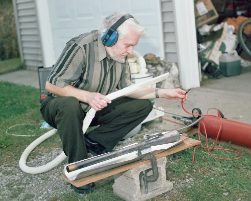
Now, get your hearing protection in place; for working up close
to a pulsejet, I use foam plugs AND plastic muffs! Start up the
spark, and start your blower. Your blower nozzle can be slightly
to one side of the tail pipe, but aim it directly at the intake
flare. A shop vac with crevice tool can be as far as 8-10 inches
from the intake opening; a big leaf blower can be a foot or more
away - what you want is a gentle but high-speed stream flowing
into the engine through the intake flare. You should just be able
to hear a low 'howl' from the intake, not a "mighty rushing wind."
Now, start to ease open the fuel needle valve while keeping the
air stream steady into the intake. You should soon get a fairly
loud rumble as combustion begins. Open it up gradually, and you
should start to get a loud roar from explosions in the chamber -
a loud, horn-like noise! If this seems steady, try briefly aiming
the blower air slightly away from the intake. If the roar stops,
increase the fuel a little as you re-aim the air back at the
intake to restore explosive combustion [this will probably start
out with a loud bang, due to accumulated fuel in the engine].
Continue feeling your way along until the roar sustains when the
air is aimed away from the intake. Now, open the fuel valve just
a hair more to richen the mixture to maintain running, and switch
off the spark - the engine should keep on roaring! Now, remove
the high voltage leads from the engine so the wires won't be
ruined by the engine heat:
To set up for testing, clamp the test mount down to something
good and heavy [I use a broken 'cement' construction block]. Set
up the propane with the regulator, needle valve and fuel hose,
and attach the other end of the hose to the fuel pipe. As alluded
to earlier, wrap the last few inches of hose and the fuel pipe
fitting in aluminum foil to protect them from the heat. Insert
the fuel pipe in the intake and provide slight tension in the
hose to make sure the fuel pipe stays put. Make sure the needle
valve is closed and the regulator screw is turned all the way
out [0 pressure], and open the fuel cylinder valve. Now the
fuel pressure can be set on the regulator - 12-15 PSI is enough.
'Crack' the needle valve just long enough to be sure that gas is
flowing, and re-close it. Next, connect up the battery and
switch, and the high-voltage leads between the coil and the spark
plug and engine, making sure the 'hot' lead is the one going to
the plug. Switch the coil on for a second to test it - don't be
surprised if there's a quick bang from the engine due to the
small amount of fuel vapor left there!
Now, get your hearing protection in place; for working up close
to a pulsejet, I use foam plugs AND plastic muffs! Start up the
spark, and start your blower. Your blower nozzle can be slightly
to one side of the tail pipe, but aim it directly at the intake
flare. A shop vac with crevice tool can be as far as 8-10 inches
from the intake opening; a big leaf blower can be a foot or more
away - what you want is a gentle but high-speed stream flowing
into the engine through the intake flare. You should just be able
to hear a low 'howl' from the intake, not a "mighty rushing wind."
Now, start to ease open the fuel needle valve while keeping the
air stream steady into the intake. You should soon get a fairly
loud rumble as combustion begins. Open it up gradually, and you
should start to get a loud roar from explosions in the chamber -
a loud, horn-like noise! If this seems steady, try briefly aiming
the blower air slightly away from the intake. If the roar stops,
increase the fuel a little as you re-aim the air back at the
intake to restore explosive combustion [this will probably start
out with a loud bang, due to accumulated fuel in the engine].
Continue feeling your way along until the roar sustains when the
air is aimed away from the intake. Now, open the fuel valve just
a hair more to richen the mixture to maintain running, and switch
off the spark - the engine should keep on roaring! Now, remove
the high voltage leads from the engine so the wires won't be
ruined by the engine heat:
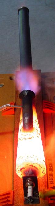
 All that's left is to shut off your blower and sit back and enjoy
the roar of the 'Short Lady' Focused Wave Valveless Pulsejet -
note the front end getting good and hot after just a few seconds
of running:
All that's left is to shut off your blower and sit back and enjoy
the roar of the 'Short Lady' Focused Wave Valveless Pulsejet -
note the front end getting good and hot after just a few seconds
of running:
 It should be able to run as long as you want [or until the
propane cylinder 'freezes up' from the internal pressure drop] -
just shut the fuel off at the needle valve to stop it.
IX. Steve's Short Lady Prototype Run-Time Photo Gallery
Previous section Back to Contents Top of page To top of page 1
Subscribe to jetZILLA Online Magazine (it's FREE!)
During the summer of 2004, Connecticut high school
student Steve Bukowski decided to build a working
prototype of my "five dollar valveless pulsejet", the
Elektra I, which I had just designed, built and
successfully run. Steve built his in just a few hours,
and got it running with little difficulty. Here's Steve's
parody of my 'What every man needs is a jet to
fly' promotional shot, featuring the Elektra I [yes,
that thing under his hand is the engine!]:
It should be able to run as long as you want [or until the
propane cylinder 'freezes up' from the internal pressure drop] -
just shut the fuel off at the needle valve to stop it.
IX. Steve's Short Lady Prototype Run-Time Photo Gallery
Previous section Back to Contents Top of page To top of page 1
Subscribe to jetZILLA Online Magazine (it's FREE!)
During the summer of 2004, Connecticut high school
student Steve Bukowski decided to build a working
prototype of my "five dollar valveless pulsejet", the
Elektra I, which I had just designed, built and
successfully run. Steve built his in just a few hours,
and got it running with little difficulty. Here's Steve's
parody of my 'What every man needs is a jet to
fly' promotional shot, featuring the Elektra I [yes,
that thing under his hand is the engine!]:
 Photo Copyright 2004 Steve Bukowsky
After school started at the end of summer, Steve was looking
for a more challenging pulsejet project, since he once again
had access to his school's metal shop equipment. So, when I
announced a new design, the 'Short Lady', on Kenneth
Moller's Valveless Pulsejet Forum, Steve asked if he could
be the first one to try to build one. Since I had no way of
rolling the sheet steel cones, I was happy to have him give
it a go.
Since Steve built [and ran!] the world's first prototype of
the Focused Wave engine, he was able to get the first photos
of it, including some fine shots of it running in almost
total darkness. Some of these lose a lot due to size reduction
for this page, unfortunately, but they still give a good idea
of the drama of building and running the 'Short Lady':
Steve's test mount - he doesn't like welded-on
mounting lugs, so he just held it at the spark plug
and the tailpipe:
Photo Copyright 2004 Steve Bukowsky
After school started at the end of summer, Steve was looking
for a more challenging pulsejet project, since he once again
had access to his school's metal shop equipment. So, when I
announced a new design, the 'Short Lady', on Kenneth
Moller's Valveless Pulsejet Forum, Steve asked if he could
be the first one to try to build one. Since I had no way of
rolling the sheet steel cones, I was happy to have him give
it a go.
Since Steve built [and ran!] the world's first prototype of
the Focused Wave engine, he was able to get the first photos
of it, including some fine shots of it running in almost
total darkness. Some of these lose a lot due to size reduction
for this page, unfortunately, but they still give a good idea
of the drama of building and running the 'Short Lady':
Steve's test mount - he doesn't like welded-on
mounting lugs, so he just held it at the spark plug
and the tailpipe:
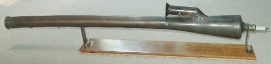 Photo Copyright 2004 Steve Bukowsky
Top view from the front and a rear view from up close:
Photo Copyright 2004 Steve Bukowsky
Top view from the front and a rear view from up close:
 Both photos Copyright 2004 Steve Bukowsky
A nice view of the combustion chamber:
Both photos Copyright 2004 Steve Bukowsky
A nice view of the combustion chamber:
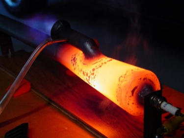 Photo Copyright 2004 Steve Bukowsky
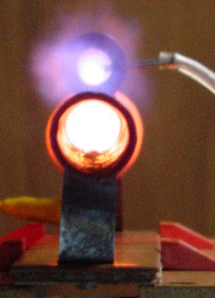
Good top view showing flame ejection from the
rear-facing intake:
Photo Copyright 2004 Steve Bukowsky
Good top view showing flame ejection from the
rear-facing intake:
 Photo Copyright 2004 Steve Bukowsky
Steve's homebuilt rig for thrust measurement, using
precision lab scale on loan from school:
Photo Copyright 2004 Steve Bukowsky
Steve's homebuilt rig for thrust measurement, using
precision lab scale on loan from school:
 Photo Copyright 2004 Steve Bukowsky
Another shot of the thrust measurement setup, showing
the entire test equipment setup - starting air [he used a
compressor and hand-held valve], propane setup and
ignition system:
Photo Copyright 2004 Steve Bukowsky
Another shot of the thrust measurement setup, showing
the entire test equipment setup - starting air [he used a
compressor and hand-held valve], propane setup and
ignition system:
 Photo Copyright 2004 Steve Bukowsky
Previous section Back to Contents Top of page To top of page 1
Subscribe to jetZILLA Online Magazine (it's FREE!)
Photo Copyright 2004 Steve Bukowsky
Previous section Back to Contents Top of page To top of page 1
Subscribe to jetZILLA Online Magazine (it's FREE!)
 All film processing and negative
scanning for Larry's shots was done by
Multi Media Imaging
1526 Walnut Street
Des Moines, Iowa USA 50309
515-309-3456
www.multi-media-inc.com
All film processing and negative
scanning for Larry's shots was done by
Multi Media Imaging
1526 Walnut Street
Des Moines, Iowa USA 50309
515-309-3456
www.multi-media-inc.com
|
|