Photo Diary: How I Built the "Maggie Muggs" Low-Speed
Ramjet Prototype at home in my basement, using
ordinary hand tools and a handful of discount-store
materials, with NO WELDING, for under $60 US - PART I
by Larry Cottrill, Editor, jetZILLA Online Magazine
- All photos this page Copyright 2003 Larry Cottrill -
Table of Contents [Sections I-IV below]:
I. The parts lineup [28 August 2003]
II. The tubular truss engine mounts [28 August 2003]
III. Building the diffuser section [04 September 2003]
IV. Bonding the diffuser/flameholder subassembly to
the combustion chamber/nozzle shell [12 September 2003]
Table of Contents [Sections V-VIII go on to Page 2]
V. Final major assembly steps [22 September 2003]
VI. Details, details [22 September 2003]
VII. Fuel and ignition system work [29 September 2003]
VIII. Finishing up [03 October 2003]:
Table of Contents [Maggie Muggs Test Firing Page go on to Page 3]:
I. Ben Koopman's Maggie Muggs Clone [April 2005]
II. Maggie Muggs Testing Plan, Hints and Tips
I. The parts lineup [28 August 2003]:
Next section Back to Contents Top of page Page 2 Page 3
Subscribe to jetZILLA Online Magazine (it's FREE!)
 II. The tubular truss engine mounts [28 August 2003]:
Previous section Next section Back to Contents Top of page Page 2 Page 3
Subscribe to jetZILLA Online Magazine (it's FREE!)
Gluing up an N-strut in my first gluing jig - the opposite strut,
semi-finished, and the fully cut rails are to the left. The rails
are .5 x .75 x 1/16 inch aluminum angle; the N-struts are cut
from the .25 OD titanium tubing contributed by my friend
Mark 'Thixis':
II. The tubular truss engine mounts [28 August 2003]:
Previous section Next section Back to Contents Top of page Page 2 Page 3
Subscribe to jetZILLA Online Magazine (it's FREE!)
Gluing up an N-strut in my first gluing jig - the opposite strut,
semi-finished, and the fully cut rails are to the left. The rails
are .5 x .75 x 1/16 inch aluminum angle; the N-struts are cut
from the .25 OD titanium tubing contributed by my friend
Mark 'Thixis':
 The N-struts resting against a cardboard jig to align them
properly, with just enough J-B Weld to tack them to the rails:
The N-struts resting against a cardboard jig to align them
properly, with just enough J-B Weld to tack them to the rails:
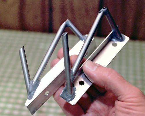
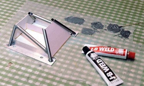 The finished engine mounts, fully reinforced with J-B Weld -
left mount in foreground, right mount behind:
The finished engine mounts, fully reinforced with J-B Weld -
left mount in foreground, right mount behind:
 III. Building the diffuser section [04 September 2003]:
Previous section Next section Back to Contents Top of page Page 2 Page 3
Subscribe to jetZILLA Online Magazine (it's FREE!)
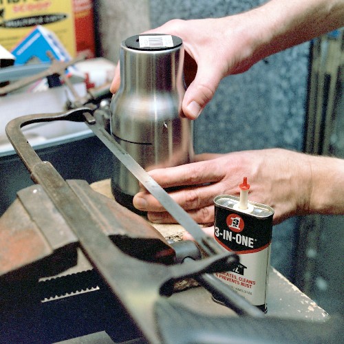
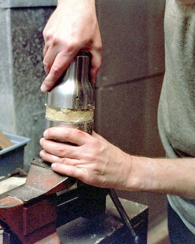
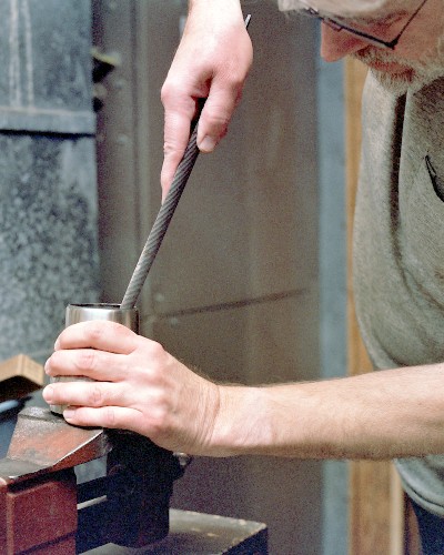
Here's a shot of cutting the groove around the mug shell. The mug
is rotated counterclockwise as seen from the top, with the saw
oriented as shown [for a left-handed blacksmith, set it all up
just the opposite way round]. I oiled the hacksaw blade, but
couldn't tell whether this really helped any - it was slow going:
III. Building the diffuser section [04 September 2003]:
Previous section Next section Back to Contents Top of page Page 2 Page 3
Subscribe to jetZILLA Online Magazine (it's FREE!)
Here's a shot of cutting the groove around the mug shell. The mug
is rotated counterclockwise as seen from the top, with the saw
oriented as shown [for a left-handed blacksmith, set it all up
just the opposite way round]. I oiled the hacksaw blade, but
couldn't tell whether this really helped any - it was slow going:
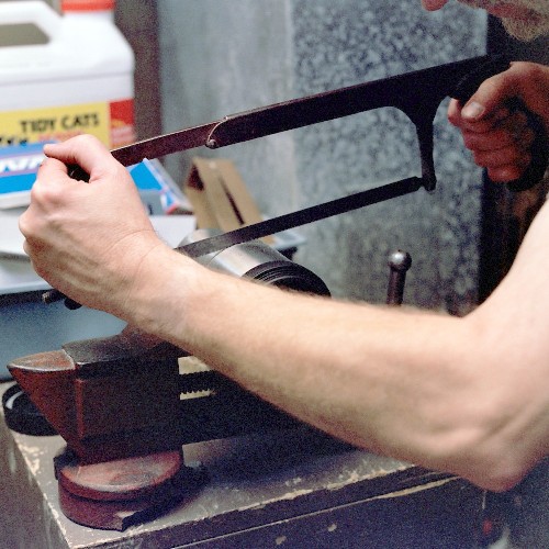
 I tried starting the cut with the jeweler's saw, but found it
impossible to get a good starting cut, so I just ended up working
my way around it with the hacksaw until I knew I'd gotten fully
through it all around. The piece had to be moved in the vise jaws
four or five times:
I tried starting the cut with the jeweler's saw, but found it
impossible to get a good starting cut, so I just ended up working
my way around it with the hacksaw until I knew I'd gotten fully
through it all around. The piece had to be moved in the vise jaws
four or five times:
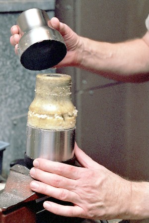
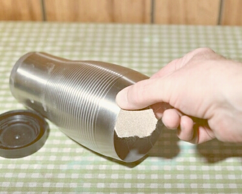
 Oddly, the lower part of the shell was not that easy to remove,
because of the friction of the insulating foam tightly formed
inside:
Oddly, the lower part of the shell was not that easy to remove,
because of the friction of the insulating foam tightly formed
inside:
 Finally, though, it does break free:
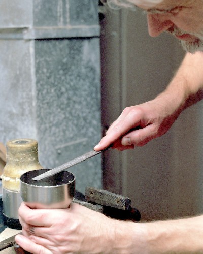
 The edge requires a few minutes of work with a flat file and a
small half-round file to make it safe to handle:
The edge requires a few minutes of work with a flat file and a
small half-round file to make it safe to handle:
 When I scraped off the non-skid ring attached to the end, I was
pleasantly surprised to find two little holes, so it was easy to
thread the jeweler's saw through to get a good start on the cut.
I just worked my way around, a bit inside the edge of the flat
end. Again, the piece had to be re-chucked in the vise a few
times; and, as predicted, I went through 6 or 7 saw blades to get
the whole end cut out. Unfortunately, neither the blade nor the
progressing saw kerf shows in the picture, since they are about
the width of a horse hair. It took about 45 minutes of sawing and
changing blades to complete the cut:
When I scraped off the non-skid ring attached to the end, I was
pleasantly surprised to find two little holes, so it was easy to
thread the jeweler's saw through to get a good start on the cut.
I just worked my way around, a bit inside the edge of the flat
end. Again, the piece had to be re-chucked in the vise a few
times; and, as predicted, I went through 6 or 7 saw blades to get
the whole end cut out. Unfortunately, neither the blade nor the
progressing saw kerf shows in the picture, since they are about
the width of a horse hair. It took about 45 minutes of sawing and
changing blades to complete the cut:
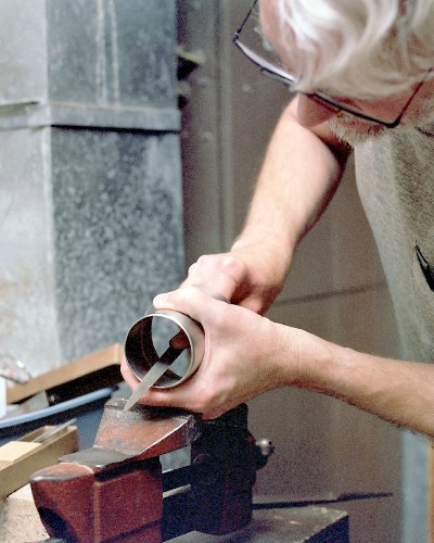
 Even though the jeweler's saw is capable of accurate work, I
didn't try for real smoothness or precision. A fairly coarse
half-round file was perfect for evening up the hole - this only
took ten minutes or so:
Even though the jeweler's saw is capable of accurate work, I
didn't try for real smoothness or precision. A fairly coarse
half-round file was perfect for evening up the hole - this only
took ten minutes or so:
 Then, a much smaller and finer half-round was used to smooth up
the opening for safe handling and inlet streamlining:
Then, a much smaller and finer half-round was used to smooth up
the opening for safe handling and inlet streamlining:
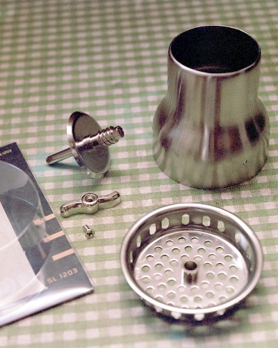
 The finished diffuser behind the 'draggy flameholder'. All the
small parts of the sink basket strainer are removed and discarded.
Note the wonderful array of apertures in this high-quality
stainless strainer - a near-perfect 'burner grill':
The finished diffuser behind the 'draggy flameholder'. All the
small parts of the sink basket strainer are removed and discarded.
Note the wonderful array of apertures in this high-quality
stainless strainer - a near-perfect 'burner grill':
 Both the inside edge of the diffuser [large end] and the entire
rolled rim of the flameholder have been roughened with sandpaper.
A small bead of J-B Weld has been applied to the INSIDE of the
diffuser rim. Here, I apply a HEAVY bead of J-B Weld over the
whole surface of the flameholder rim:
Both the inside edge of the diffuser [large end] and the entire
rolled rim of the flameholder have been roughened with sandpaper.
A small bead of J-B Weld has been applied to the INSIDE of the
diffuser rim. Here, I apply a HEAVY bead of J-B Weld over the
whole surface of the flameholder rim:
 When the diffuser is inverted and lowered into place on this rim,
the two beads of cement will blend together to form a smooth,
strong 'glue fillet' that will lock the pieces together without
the chance of even the slightest gap, with just the slightest
bead of J-B Weld visible all around the outside.
IV. Bonding the diffuser/flameholder subassembly to
the combustion chamber/nozzle shell [12 September 2003]:
Previous section Next section Back to Contents Top of page Page 2 Page 3
Subscribe to jetZILLA Online Magazine (it's FREE!)
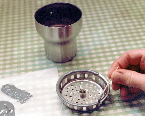
There is a significant gap [a couple of millimeters] between the
OD of the rear of the diffuser assembly and the ID of the front
edge of the combustor shell. A ring of solid J-B Weld is formed
around the diffuser rear edge to a depth of about 3/8 inch [about
8mm] to take up this difference. Believe it or not, the TOP
inside plastic rim of the Wal-Mart mug looked like just the right
dimensions to work as a mold for this epoxy ring. The trick is to
make sure the J-B Weld sticks to the stainless but not to the
plastic; so I smeared a thin coating of vegetable oil all over
the plastic rim internal surfaces. Then, a heavy coating of J-B
Weld was run around the rear diffuser where the flameholder is
bonded on, and this is then lowered, flameholder down, into the
top of the mug. J-B Weld is added by toothpick to finish filling
the gap, right up past the top of the plastic rim:
When the diffuser is inverted and lowered into place on this rim,
the two beads of cement will blend together to form a smooth,
strong 'glue fillet' that will lock the pieces together without
the chance of even the slightest gap, with just the slightest
bead of J-B Weld visible all around the outside.
IV. Bonding the diffuser/flameholder subassembly to
the combustion chamber/nozzle shell [12 September 2003]:
Previous section Next section Back to Contents Top of page Page 2 Page 3
Subscribe to jetZILLA Online Magazine (it's FREE!)
There is a significant gap [a couple of millimeters] between the
OD of the rear of the diffuser assembly and the ID of the front
edge of the combustor shell. A ring of solid J-B Weld is formed
around the diffuser rear edge to a depth of about 3/8 inch [about
8mm] to take up this difference. Believe it or not, the TOP
inside plastic rim of the Wal-Mart mug looked like just the right
dimensions to work as a mold for this epoxy ring. The trick is to
make sure the J-B Weld sticks to the stainless but not to the
plastic; so I smeared a thin coating of vegetable oil all over
the plastic rim internal surfaces. Then, a heavy coating of J-B
Weld was run around the rear diffuser where the flameholder is
bonded on, and this is then lowered, flameholder down, into the
top of the mug. J-B Weld is added by toothpick to finish filling
the gap, right up past the top of the plastic rim:
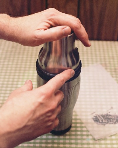
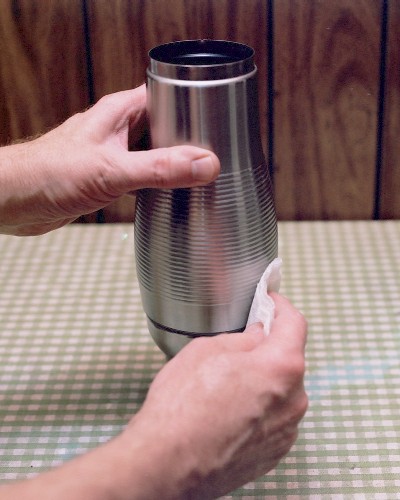
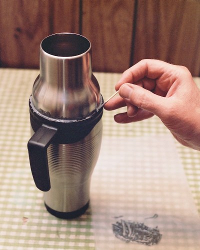 The fingertip is used to smooth out the top edge and remove the
slight excess. The thin film of J-B Weld left on the outside of
the diffuser shell is of no consequence:
The fingertip is used to smooth out the top edge and remove the
slight excess. The thin film of J-B Weld left on the outside of
the diffuser shell is of no consequence:
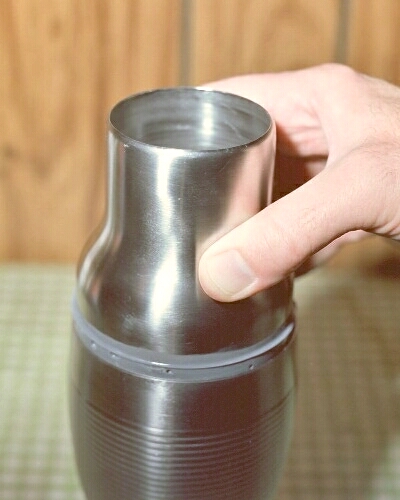
 After allowing full curing time, the finished molded ring is
popped out of the mold by wiggling the diffuser [it comes out
easily] - note the inevitable small air voids; these will be
individually filled in with J-B Weld during the operation of
bonding to the combustor shell:
After allowing full curing time, the finished molded ring is
popped out of the mold by wiggling the diffuser [it comes out
easily] - note the inevitable small air voids; these will be
individually filled in with J-B Weld during the operation of
bonding to the combustor shell:
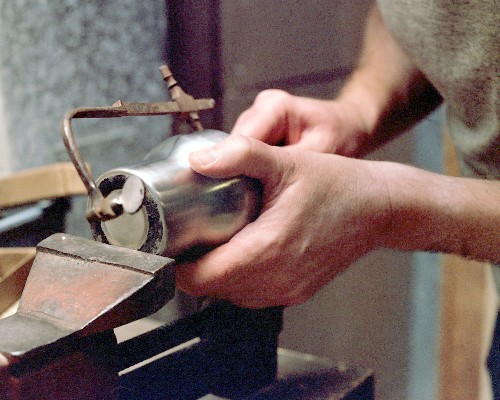
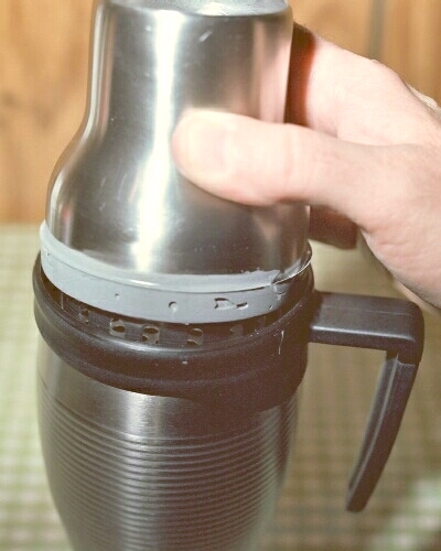 Now the Wal-Mart mug is disassembled, and the top rim of the
stainless shell is smoothed with a small file to remove slight
burrs. This is a trial fit of the epoxy ring into the edge of
the shell. Note the formed ridge of epoxy; the shell slides
easily over the main body of the ring, but balks at this ridge,
which will assure that the shell is perfectly aligned with the
diffuser assembly:
Now the Wal-Mart mug is disassembled, and the top rim of the
stainless shell is smoothed with a small file to remove slight
burrs. This is a trial fit of the epoxy ring into the edge of
the shell. Note the formed ridge of epoxy; the shell slides
easily over the main body of the ring, but balks at this ridge,
which will assure that the shell is perfectly aligned with the
diffuser assembly:
 The epoxy ring must be cleaned thoroughly with strong alcohol to
make sure there is no residue of the cooking oil.
Using medium sandpaper to roughen the inside edge of the shell to
ensure solid bonding [this area is also de-greased with strong
alcohol]:
The epoxy ring must be cleaned thoroughly with strong alcohol to
make sure there is no residue of the cooking oil.
Using medium sandpaper to roughen the inside edge of the shell to
ensure solid bonding [this area is also de-greased with strong
alcohol]:
 Finally, the entire outer surface of the epoxy ring is coated with
J-B Weld and the little voids are all filled in. Then, a HEAVY
bead of J-B Weld is applied all around the INSIDE of the front
edge of the shell. The diffuser assembly is inverted and the shell
is lowered into place around it, until it comes to rest on the
molded ridge. This is the orientation it is left in until the bond
is fully cured. Here, I wipe excess epoxy off the outside with a
dry paper towel; the residual film will be removed by a little
fine sanding:
Finally, the entire outer surface of the epoxy ring is coated with
J-B Weld and the little voids are all filled in. Then, a HEAVY
bead of J-B Weld is applied all around the INSIDE of the front
edge of the shell. The diffuser assembly is inverted and the shell
is lowered into place around it, until it comes to rest on the
molded ridge. This is the orientation it is left in until the bond
is fully cured. Here, I wipe excess epoxy off the outside with a
dry paper towel; the residual film will be removed by a little
fine sanding:
 Previous section Next section Back to Contents Top of page Page 2 Page 3
Subscribe to jetZILLA Online Magazine (it's FREE!)
Previous section Next section Back to Contents Top of page Page 2 Page 3
Subscribe to jetZILLA Online Magazine (it's FREE!)
 All film processing and negative
scanning for this page was done by
Multi Media Imaging
1526 Walnut Street
Des Moines, Iowa USA 50309
515-309-3456
www.multi-media-inc.com
All film processing and negative
scanning for this page was done by
Multi Media Imaging
1526 Walnut Street
Des Moines, Iowa USA 50309
515-309-3456
www.multi-media-inc.com
|
|