Photo Diary: The "Maggie Muggs" Low-Speed
Ramjet Prototype - PART III - TEST FIRINGS
by Larry Cottrill, Editor, jetZILLA Online Magazine
- All photos this page Copyright 2003 Larry Cottrill -
Table of Contents [Construction Sections I-IV go back to Page 1]:
I. The parts lineup [28 August 2003]
II. The tubular truss engine mounts [28 August 2003]
III. Building the diffuser section [04 September 2003]
IV. Bonding the diffuser/flameholder subassembly to
the combustion chamber/nozzle shell [12 September 2003]
Table of Contents [Construction Sections V-VIII go back to Page 2]:
V. Final major assembly steps [22 September 2003]
VI. Details, details [22 September 2003]
VII. Fuel and ignition system work [29 September 2003]
VIII. Finishing up [03 October 2003]
Table of Contents [Maggie Muggs Test Firing Page]:
I. Ben Koopman's Maggie Muggs Clone [April 2005]
II. Maggie Muggs Testing Plan, Hints and Tips
I. Ben Koopman's Maggie Muggs Clone [April 2005]:
Previous section Next section Back to Contents Top of page Page 1 Page 2
Subscribe to jetZILLA Online Magazine (it's FREE!)
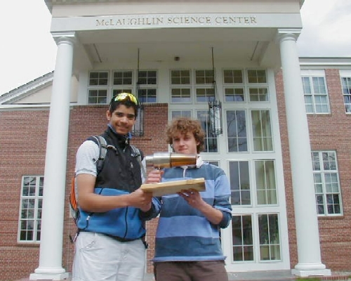
The first successful test firing of a Maggie Muggs type ramjet engine
was by Ben Koopman and teacher Randy Autrey at Gould Academy in
Maine, USA during the last week in April, 2005:
Ben looks on as his teacher Randy Autrey attempts to balance
the air input and fuel flow. It's easy to get too much fuel for the
airflow, as shown here. However, Randy claims that once you get
used to it, his 'squeeze bottle' method of delivering liquid fuel is
quite easy to use, since it gives you instant control over the fuel
pressure. From the mugs to the air source, Ben mostly used what they
found available at school, so his out-of-pocket cost for the project
was very low. One thing I recommended to Randy is that they try to
get a good leaf blower; that would provide a lot more air for cooling.
However, their initial tests were with what they had available, a
standard 'shop vac', and it seems to work well enough:
 When more airflow and/or less fuel flow is applied, the flame starts
to look somewhat better - we're moving towards "lean" combustion:
When more airflow and/or less fuel flow is applied, the flame starts
to look somewhat better - we're moving towards "lean" combustion:
 Continuing to lean out the burn. It looks like there's enough flame
and noise at this point that the test run is beginning to draw a
crowd. The mug parts were from teachers that were willing to donate
their used coffee mugs to the project, so these parts aren't exactly
like the ones shown in the plans; note, however, how Ben chose a mug
shell that has a well-developed combustion chamber zone and a good
long, smooth cone for the tail section - exactly the right approach!
Continuing to lean out the burn. It looks like there's enough flame
and noise at this point that the test run is beginning to draw a
crowd. The mug parts were from teachers that were willing to donate
their used coffee mugs to the project, so these parts aren't exactly
like the ones shown in the plans; note, however, how Ben chose a mug
shell that has a well-developed combustion chamber zone and a good
long, smooth cone for the tail section - exactly the right approach!
 Leaning out the combustion even more makes the flame much less
visible, but significantly louder [note that the unlookers are starting
to back off a little!]. The sink strainer flameholder is one of the few
parts that had to be purchased new for the project; it keeps the
flame back in the tail section where we need it [unfortunately, the
flameholder can't be seen in any of these photos]:
Leaning out the combustion even more makes the flame much less
visible, but significantly louder [note that the unlookers are starting
to back off a little!]. The sink strainer flameholder is one of the few
parts that had to be purchased new for the project; it keeps the
flame back in the tail section where we need it [unfortunately, the
flameholder can't be seen in any of these photos]:
 Once you get a really good lean run, the noise is a pretty intense
'jet noise' roar, and in daylight the visible flame almost disappears.
This is exactly the way your jet ought to be running. However, this is
also a very hot way to run, and the epoxy construction can't be
expected to take this for too long:
Once you get a really good lean run, the noise is a pretty intense
'jet noise' roar, and in daylight the visible flame almost disappears.
This is exactly the way your jet ought to be running. However, this is
also a very hot way to run, and the epoxy construction can't be
expected to take this for too long:
 Finally, fuel pressure is cut back enough that flameout occurs,
before the glued construction suffers any damage. Ben keeps the
air flowing in for a while to cool things down:
Finally, fuel pressure is cut back enough that flameout occurs,
before the glued construction suffers any damage. Ben keeps the
air flowing in for a while to cool things down:
 I first heard of this project via email back in mid-April, 2005, and briefly
corresponded with Randy Autrey a few times to offer encouragement and
minor suggestions. On May 1, I received the photos shown here, attached
to the following email from Randy summarizing successful construction and
testing of Ben's Maggie Muggs clone ramjet:
Larry,
You may use any or all of the following on jetZILLA or
wherever you would like.
My name is Randy Autrey and I work at Gould Academy,
a college preparatory boarding and day school in the
western mountains of Maine. I am a private pilot and I
also fly model airplanes. One of our students at
Gould, Ben K., saw the Maggie Muggs project on the
internet and asked if I could use it to fly one of my
model airplanes. I told him it looked like a fun
project and that we should build and test it. That is
exactly what we did.
We grabbed some freebie mugs from faculty members and
bought a sink strainer at Wal Mart. Ben used a dremel
tool to cut the mugs and we drilled a hole for the
brass tube injection system. We used JB weld to
assemble the mugs with the understanding that it was
only rated for 600 degrees F. Our first test fire was
with the small drilled brass tube which was flattened
in the center for a spray bar. We used a model
airplane fuel bottle to pressurize the gas mixture for
injection. The mug did ignite and produce a flame. It
was immediately obvious that we did not have enough
fuel. We went back to the lab to change the injection.
This time we just flattened the end of the brass
tubing and JB welded the tube to the front of the mug.
As you can see from the pictures we had plenty of
fuel. I like the pressurized bottle injection system
because you can control the flow. We started out with
light pressure during ignition and increased fuel
delivery as we increased shop vac air flow. You can
see this transition in the series of pictures of the
big flame 'blow torch' look during ignition to the
chiseled flame near the end. Just when the sound
changes and the flame becomes a chiseled point it is
time to shut down. This produces a lot of heat very
quickly when it hits efficiency.
This is a great project with very low cost and
construction effort. This was great for the students.
We are very pleased with the results. This Maggie Muggs
really draws a crowd.
We are planning on firing it again but this time we
will run it at night to see the transition from
ignition to chiseled flame. We hope to have a video
clip available soon. Stay tuned for more. We started
working on a valveless pulsejet so we will let you
know how that works out.
I would like to thank Larry for a fun design and all
of the emails he sent. Great job Larry.
Randy Autrey
Gould Academy
After test firing, Ben's Maggie Muggs clone is still in good
condition - Ben can take pride in building a finely-crafted,
nice-running engine!
I first heard of this project via email back in mid-April, 2005, and briefly
corresponded with Randy Autrey a few times to offer encouragement and
minor suggestions. On May 1, I received the photos shown here, attached
to the following email from Randy summarizing successful construction and
testing of Ben's Maggie Muggs clone ramjet:
Larry,
You may use any or all of the following on jetZILLA or
wherever you would like.
My name is Randy Autrey and I work at Gould Academy,
a college preparatory boarding and day school in the
western mountains of Maine. I am a private pilot and I
also fly model airplanes. One of our students at
Gould, Ben K., saw the Maggie Muggs project on the
internet and asked if I could use it to fly one of my
model airplanes. I told him it looked like a fun
project and that we should build and test it. That is
exactly what we did.
We grabbed some freebie mugs from faculty members and
bought a sink strainer at Wal Mart. Ben used a dremel
tool to cut the mugs and we drilled a hole for the
brass tube injection system. We used JB weld to
assemble the mugs with the understanding that it was
only rated for 600 degrees F. Our first test fire was
with the small drilled brass tube which was flattened
in the center for a spray bar. We used a model
airplane fuel bottle to pressurize the gas mixture for
injection. The mug did ignite and produce a flame. It
was immediately obvious that we did not have enough
fuel. We went back to the lab to change the injection.
This time we just flattened the end of the brass
tubing and JB welded the tube to the front of the mug.
As you can see from the pictures we had plenty of
fuel. I like the pressurized bottle injection system
because you can control the flow. We started out with
light pressure during ignition and increased fuel
delivery as we increased shop vac air flow. You can
see this transition in the series of pictures of the
big flame 'blow torch' look during ignition to the
chiseled flame near the end. Just when the sound
changes and the flame becomes a chiseled point it is
time to shut down. This produces a lot of heat very
quickly when it hits efficiency.
This is a great project with very low cost and
construction effort. This was great for the students.
We are very pleased with the results. This Maggie Muggs
really draws a crowd.
We are planning on firing it again but this time we
will run it at night to see the transition from
ignition to chiseled flame. We hope to have a video
clip available soon. Stay tuned for more. We started
working on a valveless pulsejet so we will let you
know how that works out.
I would like to thank Larry for a fun design and all
of the emails he sent. Great job Larry.
Randy Autrey
Gould Academy
After test firing, Ben's Maggie Muggs clone is still in good
condition - Ben can take pride in building a finely-crafted,
nice-running engine!
 II. Maggie Muggs Testing Plan, Hints and Tips:
Previous section Back to Contents Top of page Page 1 Page 2
Subscribe to jetZILLA Online Magazine (it's FREE!)
MAGGIE MUGGS GENERAL TEST FIRING PLAN:
1. Secure engine to test bench, locking heat shield in place
2. Secure blower loosely to test bench
3. Align blower carefully on engine centerline, BOTH horizontally
and vertically while gradually tightening blower mounting
4. Make final check of blower alignment and spacing and secure
tight to test bench - be sure airflow covers entire engine
exterior!
5. Start spark ignition and verify good spark by visual sighting
from behind exhaust nozzle
6. Start blower and again verify good spark by sighting through nozzle
7. If possible, make preliminary thrust measurement - this is the
blower thrust minus total engine drag
8. Open fuel valve until combustion is achieved
9. Continue to open fuel valve until large, rich-burning flame
is observable - if this isn't obtainable, stop the test, your
fuel supply or valve is inadequate - otherwise, continue:
10. If possible, measure and record the rich-running thrust and
fuel flow
11. Reduce fuel flow to leaner running condition, pulling the flame
forward inside the nozzle - run for a few seconds and observe
the J-B Weld seam at the engine mid-point - if any signs of the
epoxy softening, shut off the fuel and allow time for the blower
to cool the engine - otherwise, continue:
12. Reduce fuel flow further, pulling the flame forward into the
aft region of the combustion chamber - if combustion is
observed inside the diffuser section, shut off the fuel and
allow time for the blower to cool the engine! - otherwise,
continue:
13. Shut off the spark ignition system - if the engine quits, shut
off the fuel and allow time for cooling! - otherwise, continue:
14. Try to obtain a running condition where only the nozzle zone is
visibly red hot, with no red heating of the combustion chamber -
if this is not obtainable, shut down and allow the blower to
cool the engine - otherwise, continue:
15. Run for several seconds and again observe the engine mid-point
seam - if there are signs of the epoxy softening, shut off the
fuel and allow time for the blower to cool the engine -
otherwise, continue:
16. If possible, measure and record the lean-running thrust and
fuel flow and the diffuser static pressure
17. Finish testing by quickly shutting off the fuel flow completely
18. Allow the blower to run until the entire engine structure is
cool enough to touch safely, then shut down blower
19. Adjust measured thrust figures by subtracting the unpowered
thrust value obtained in Step 7, above
MAGGIE MUGGS TESTING HINTS & TIPS:
Cooling air is just as important as combustion air!
1. Use the biggest air mover you can obtain. My choice was the
electrically powered Black & Decker Leaf Hog, capable of
120 MPH maximum air velocity, but any large-volume, high
velocity blower will work. A big shop vacuum is probably
just barely adequate for this application.
2. Position your air mover far enough from the engine intake so
that as much of the engine exterior as possible is constantly
bathed in high-speed airflow during and after a run. There
MUST be good airflow over the entire rear section of the
engine!
3. Make sure you have a 'quick cutoff' fuel valve that will let
you shut off fuel immediately if there is a failure of your
air mover. In fact, if you can figure out how to do it, it
wouldn't be a bad idea to route your fuel through an electric
valve with an air-driven switch for automatic shutdown in
case of air supply failure!
4. After a normal test run, make sure you keep your blower running
until the entire engine cools, to protect the J-B Weld bonds.
Even thin stainless holds heat a surprisingly long time and
heat flow from the tail cone forward after the run could
still lead to softening or degradation of the epoxy bead at
the engine mid-point if cooling is stopped too soon!
Start out running rich and work toward lean!
1. As soon as possible after you get ignition, try to get enough
fuel flowing to develop a rich-burning flame. This will keep
most of the combustion well to the rear, to minimize heat
buildup in the tail cone and, therefore, heat conduction to
the front end.
2. After you establish rich combustion, you can start leaning
the air/fuel mixture, gradually pulling the flame front
forward in the rear section of the engine, while regularly
testing the midsection J-B Weld bead for softness.
3. If the midsection epoxy bead starts to soften, you have
reached the limit of how lean you can set up the run with
the cooling you have available. At this point, it's time to
shut down the fuel [while letting the air cool down your
engine] until you can find a more effective air supply.
Start out with slow-burning fuel!
1. Start your testing with a slow-burning vapor fuel such as
propane or butane. That will make it easy to control the
position of the flame front in the engine by adjusting the
fuel flow.
2. If your air supply is so strong that you can't get the flame
front to move forward into the tail cone, reduce the entering
air velocity by putting more distance between the air nozzle
and the engine intake. Make sure you maintain good aiming of
the air nozzle so that you will have adequate cooling air
flow!
3. If you can achieve good engine operation, then you can try
more powerful, faster flame speed fuels such as MAPP gas.
You will probably want the highest possible entering air speed
for this to keep the flame front well in the rear of the
engine, and so throttling won't become over-sensitive.
4. It is strongly recommended that you provide a fuel pressure
regulator at the supply point, so you won't be fighting
pressure changes due to changing fuel temperature:
II. Maggie Muggs Testing Plan, Hints and Tips:
Previous section Back to Contents Top of page Page 1 Page 2
Subscribe to jetZILLA Online Magazine (it's FREE!)
MAGGIE MUGGS GENERAL TEST FIRING PLAN:
1. Secure engine to test bench, locking heat shield in place
2. Secure blower loosely to test bench
3. Align blower carefully on engine centerline, BOTH horizontally
and vertically while gradually tightening blower mounting
4. Make final check of blower alignment and spacing and secure
tight to test bench - be sure airflow covers entire engine
exterior!
5. Start spark ignition and verify good spark by visual sighting
from behind exhaust nozzle
6. Start blower and again verify good spark by sighting through nozzle
7. If possible, make preliminary thrust measurement - this is the
blower thrust minus total engine drag
8. Open fuel valve until combustion is achieved
9. Continue to open fuel valve until large, rich-burning flame
is observable - if this isn't obtainable, stop the test, your
fuel supply or valve is inadequate - otherwise, continue:
10. If possible, measure and record the rich-running thrust and
fuel flow
11. Reduce fuel flow to leaner running condition, pulling the flame
forward inside the nozzle - run for a few seconds and observe
the J-B Weld seam at the engine mid-point - if any signs of the
epoxy softening, shut off the fuel and allow time for the blower
to cool the engine - otherwise, continue:
12. Reduce fuel flow further, pulling the flame forward into the
aft region of the combustion chamber - if combustion is
observed inside the diffuser section, shut off the fuel and
allow time for the blower to cool the engine! - otherwise,
continue:
13. Shut off the spark ignition system - if the engine quits, shut
off the fuel and allow time for cooling! - otherwise, continue:
14. Try to obtain a running condition where only the nozzle zone is
visibly red hot, with no red heating of the combustion chamber -
if this is not obtainable, shut down and allow the blower to
cool the engine - otherwise, continue:
15. Run for several seconds and again observe the engine mid-point
seam - if there are signs of the epoxy softening, shut off the
fuel and allow time for the blower to cool the engine -
otherwise, continue:
16. If possible, measure and record the lean-running thrust and
fuel flow and the diffuser static pressure
17. Finish testing by quickly shutting off the fuel flow completely
18. Allow the blower to run until the entire engine structure is
cool enough to touch safely, then shut down blower
19. Adjust measured thrust figures by subtracting the unpowered
thrust value obtained in Step 7, above
MAGGIE MUGGS TESTING HINTS & TIPS:
Cooling air is just as important as combustion air!
1. Use the biggest air mover you can obtain. My choice was the
electrically powered Black & Decker Leaf Hog, capable of
120 MPH maximum air velocity, but any large-volume, high
velocity blower will work. A big shop vacuum is probably
just barely adequate for this application.
2. Position your air mover far enough from the engine intake so
that as much of the engine exterior as possible is constantly
bathed in high-speed airflow during and after a run. There
MUST be good airflow over the entire rear section of the
engine!
3. Make sure you have a 'quick cutoff' fuel valve that will let
you shut off fuel immediately if there is a failure of your
air mover. In fact, if you can figure out how to do it, it
wouldn't be a bad idea to route your fuel through an electric
valve with an air-driven switch for automatic shutdown in
case of air supply failure!
4. After a normal test run, make sure you keep your blower running
until the entire engine cools, to protect the J-B Weld bonds.
Even thin stainless holds heat a surprisingly long time and
heat flow from the tail cone forward after the run could
still lead to softening or degradation of the epoxy bead at
the engine mid-point if cooling is stopped too soon!
Start out running rich and work toward lean!
1. As soon as possible after you get ignition, try to get enough
fuel flowing to develop a rich-burning flame. This will keep
most of the combustion well to the rear, to minimize heat
buildup in the tail cone and, therefore, heat conduction to
the front end.
2. After you establish rich combustion, you can start leaning
the air/fuel mixture, gradually pulling the flame front
forward in the rear section of the engine, while regularly
testing the midsection J-B Weld bead for softness.
3. If the midsection epoxy bead starts to soften, you have
reached the limit of how lean you can set up the run with
the cooling you have available. At this point, it's time to
shut down the fuel [while letting the air cool down your
engine] until you can find a more effective air supply.
Start out with slow-burning fuel!
1. Start your testing with a slow-burning vapor fuel such as
propane or butane. That will make it easy to control the
position of the flame front in the engine by adjusting the
fuel flow.
2. If your air supply is so strong that you can't get the flame
front to move forward into the tail cone, reduce the entering
air velocity by putting more distance between the air nozzle
and the engine intake. Make sure you maintain good aiming of
the air nozzle so that you will have adequate cooling air
flow!
3. If you can achieve good engine operation, then you can try
more powerful, faster flame speed fuels such as MAPP gas.
You will probably want the highest possible entering air speed
for this to keep the flame front well in the rear of the
engine, and so throttling won't become over-sensitive.
4. It is strongly recommended that you provide a fuel pressure
regulator at the supply point, so you won't be fighting
pressure changes due to changing fuel temperature:
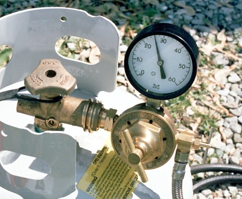 A good propane regulator and valve setup, built from an old-style Victor
high volume air regulator and needle valve. This has proved more than
ample for the fuel demands of my small pulsejet engine prototypes, and
should work fine for testing Maggie Muggs.
Photo Copyright 2004 Larry Cottrill
Test Firing 'Must Have' List:
1. Type A-B-C fire extinguisher
2. Hearing protection
3. Safety goggles
4. 'Quick shutoff' valve in fuel line
5. Largest volume blower you can find & reliable power
6. Outdoor or VERY well-ventilated 'fire safe' test site
7. Reliable fuel lines in good condition
8. Reliable ignition spark source
Test Firing 'Optional' List:
1. Thrust measurement stand for blower & engine
2. Water manometer for diffuser pressure measurement
3. Water manometer for velocity pressure measurement
4. Pressure regulator for fuel gas
Previous section Back to Contents Top of page Page 1 Page 2
Subscribe to jetZILLA Online Magazine (it's FREE!)
A good propane regulator and valve setup, built from an old-style Victor
high volume air regulator and needle valve. This has proved more than
ample for the fuel demands of my small pulsejet engine prototypes, and
should work fine for testing Maggie Muggs.
Photo Copyright 2004 Larry Cottrill
Test Firing 'Must Have' List:
1. Type A-B-C fire extinguisher
2. Hearing protection
3. Safety goggles
4. 'Quick shutoff' valve in fuel line
5. Largest volume blower you can find & reliable power
6. Outdoor or VERY well-ventilated 'fire safe' test site
7. Reliable fuel lines in good condition
8. Reliable ignition spark source
Test Firing 'Optional' List:
1. Thrust measurement stand for blower & engine
2. Water manometer for diffuser pressure measurement
3. Water manometer for velocity pressure measurement
4. Pressure regulator for fuel gas
Previous section Back to Contents Top of page Page 1 Page 2
Subscribe to jetZILLA Online Magazine (it's FREE!)
|
