Photo Diary: How I Built the "Maggie Muggs" Low-Speed
Ramjet Prototype at home in my basement, using
ordinary hand tools and a handful of discount-store
materials, with NO WELDING, for under $60 US - PART II
by Larry Cottrill, Editor, jetZILLA Online Magazine
- All photos this page Copyright 2003 Larry Cottrill -
Table of Contents [Sections I-IV go back to Page 1]:
I. The parts lineup [28 August 2003]
II. The tubular truss engine mounts [28 August 2003]
III. Building the diffuser section [04 September 2003]
IV. Bonding the diffuser/flameholder subassembly to
the combustion chamber/nozzle shell [12 September 2003]
Table of Contents [Sections V-VIII below]:
V. Final major assembly steps [22 September 2003]
VI. Details, details [22 September 2003]
VII. Fuel and ignition system work [29 September 2003]
VIII. Finishing up [03 October 2003]:
Table of Contents [Maggie Muggs Test Firing Page go on to Page 3]:
I. Ben Koopman's Maggie Muggs Clone [April 2005]
II. Maggie Muggs Testing Plan, Hints and Tips
V. Final major assembly steps [22 September 2003]:
Previous section Next section Top of page Page 1 Page 3
Subscribe to jetZILLA Online Magazine (it's FREE!)
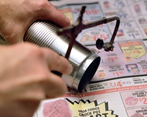
The preliminary bonding of the main assembly to the mounts is
done by lashing to the finished mounts with vinyl-insulated wire,
twisted tight:
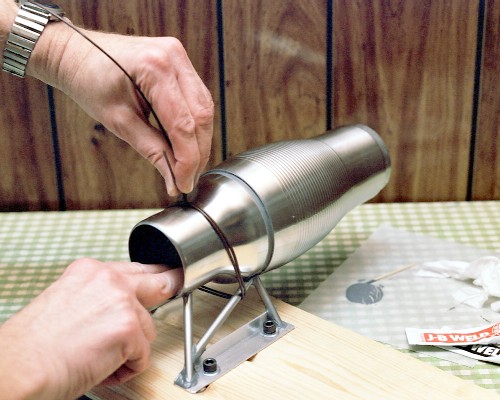 The mounts are secured, accurately aligned, to a piece of flat
scrap wood, using 1/4-20 hex head bolts & washers, with 'tee nuts'
underneath.
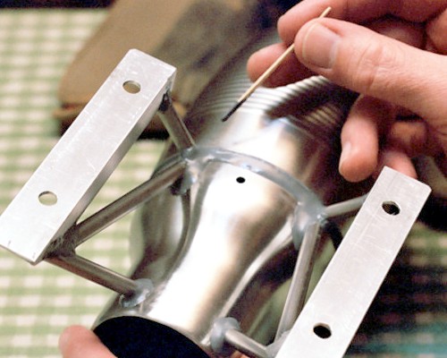
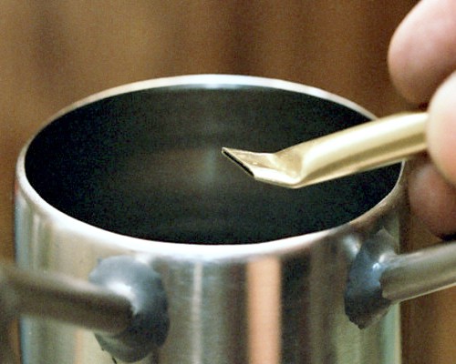
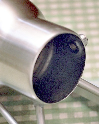
Forming the streamlining fillet at the front edge of the
combustor shell. This is along the bottom side, before the little
hole was filed into being a slot:
The mounts are secured, accurately aligned, to a piece of flat
scrap wood, using 1/4-20 hex head bolts & washers, with 'tee nuts'
underneath.
Forming the streamlining fillet at the front edge of the
combustor shell. This is along the bottom side, before the little
hole was filed into being a slot:
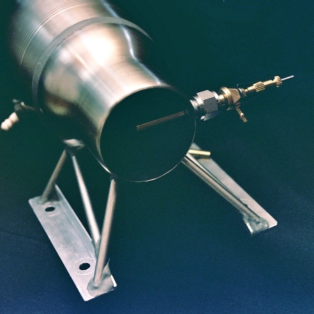
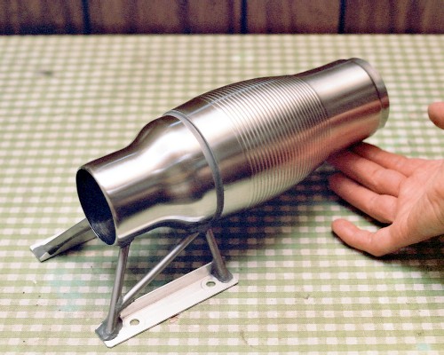
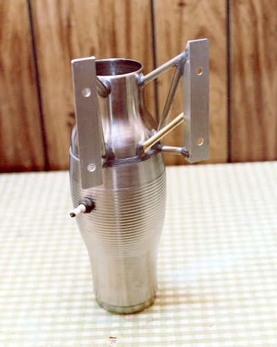
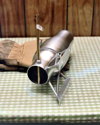
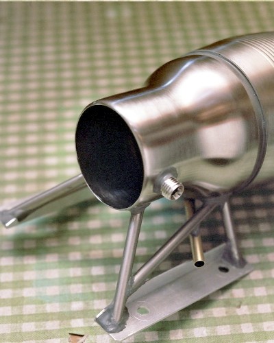
 Here's a fine shot of Maggie, basically assembled, but before
drilling out for the fuel pipe & spark plug:
Here's a fine shot of Maggie, basically assembled, but before
drilling out for the fuel pipe & spark plug:
 VI. Details, details [22 September 2003]:
Previous section Next section Back to Contents Top of page Page 1 Page 3
Subscribe to jetZILLA Online Magazine (it's FREE!)
The flattened and kinked end of the pressure tube. This part will
protrude slightly beyond the inside wall of the large part of the
diffuser, so the cut end will lie along the presumed flow path.
The tubing is 1/4-inch OD brass. The flattening is to limit
leakage from the diffuser shell when a gauge is not attached;
only a trickle of air is needed to pressurize the gauge.
VI. Details, details [22 September 2003]:
Previous section Next section Back to Contents Top of page Page 1 Page 3
Subscribe to jetZILLA Online Magazine (it's FREE!)
The flattened and kinked end of the pressure tube. This part will
protrude slightly beyond the inside wall of the large part of the
diffuser, so the cut end will lie along the presumed flow path.
The tubing is 1/4-inch OD brass. The flattening is to limit
leakage from the diffuser shell when a gauge is not attached;
only a trickle of air is needed to pressurize the gauge.
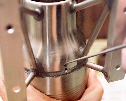
 The hole that used to hold the bottom end of the mug handle is
lengthened into a slot, using a Heller needle file. The slot is
cut in line with rearward airflow, but is slanted to one side for
the flattened tube end:
The hole that used to hold the bottom end of the mug handle is
lengthened into a slot, using a Heller needle file. The slot is
cut in line with rearward airflow, but is slanted to one side for
the flattened tube end:
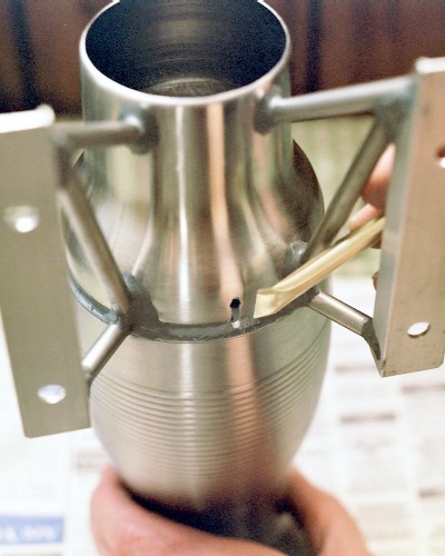
 Preparing to test fit the flattened end of the pressure tube.
This shows approximately the final orientation and location --
the outer end of the tube extends forward and down, out through
the lower space in the left-side N-strut:
Preparing to test fit the flattened end of the pressure tube.
This shows approximately the final orientation and location --
the outer end of the tube extends forward and down, out through
the lower space in the left-side N-strut:
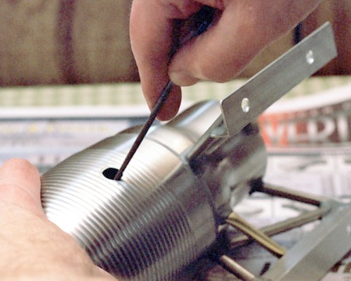
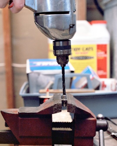
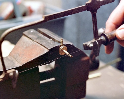
 Because of the thinness of the shell, the spark plug hole was
drilled small and filed out with another of the Heller miniature
files. This one is similar to a half-round, except that both
sides are round but ground to two different radii:
Because of the thinness of the shell, the spark plug hole was
drilled small and filed out with another of the Heller miniature
files. This one is similar to a half-round, except that both
sides are round but ground to two different radii:
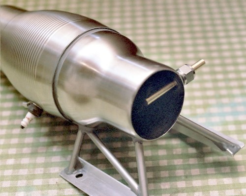
 The bottom side of the engine, showing the fully bonded engine
mounts and pressure gauge tube, with the spark plug temporarily
mounted [exact location of the plug is not critical]:
The bottom side of the engine, showing the fully bonded engine
mounts and pressure gauge tube, with the spark plug temporarily
mounted [exact location of the plug is not critical]:
 The fuel pipe mounting will be cut from a standard 1/4-inch
stainless tubing fitting. First, the fitting is drilled out 1/4-
inch ID all the way through, so the tube can pass clear through
it into the intake:
The fuel pipe mounting will be cut from a standard 1/4-inch
stainless tubing fitting. First, the fitting is drilled out 1/4-
inch ID all the way through, so the tube can pass clear through
it into the intake:
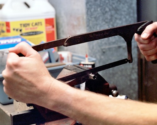
 The hardest saw cut in the entire project: Cutting off the bottom
[pipe thread] end of the fitting. I finally bought a new hacksaw
blade, and the work went MUCH faster. This will leave the machine-
thread part of the fitting to protrude through the hole in the
shell from the inside, with a thin, hexagonal flange for bonding.
The cut surface will be filed smooth, and the hole edge chamfered
for smooth passage of the fuel pipe:
The hardest saw cut in the entire project: Cutting off the bottom
[pipe thread] end of the fitting. I finally bought a new hacksaw
blade, and the work went MUCH faster. This will leave the machine-
thread part of the fitting to protrude through the hole in the
shell from the inside, with a thin, hexagonal flange for bonding.
The cut surface will be filed smooth, and the hole edge chamfered
for smooth passage of the fuel pipe:
 VII. Fuel and ignition system work [29 September 2003]:
Previous section Next section Back to Contents Top of page Page 1 Page 3
Subscribe to jetZILLA Online Magazine (it's FREE!)
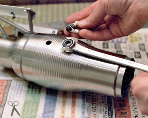
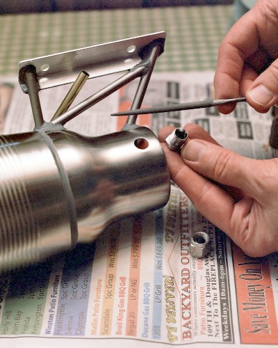
The spark plug ready to mount in the combustor shell. The box-end
wrench is fitted with a short piece of masking tape to hold the
plug mount nut up at the wrench surface, making it easy to get it
into place inside the hole so the plug can simply be threaded in.
The electrical lug is filed out to fit the plug; it not only acts
as the spark plug washer, but as a contact for the ground side of
the high-voltage ignition system during starting.
VII. Fuel and ignition system work [29 September 2003]:
Previous section Next section Back to Contents Top of page Page 1 Page 3
Subscribe to jetZILLA Online Magazine (it's FREE!)
The spark plug ready to mount in the combustor shell. The box-end
wrench is fitted with a short piece of masking tape to hold the
plug mount nut up at the wrench surface, making it easy to get it
into place inside the hole so the plug can simply be threaded in.
The electrical lug is filed out to fit the plug; it not only acts
as the spark plug washer, but as a contact for the ground side of
the high-voltage ignition system during starting.
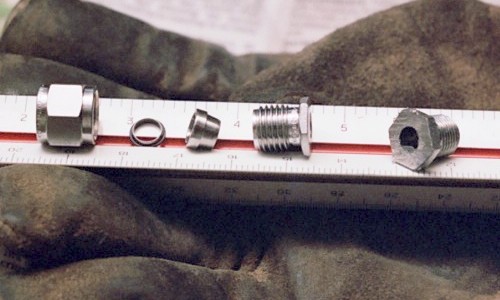
 Parts of the fuel pipe mount, after cutting and filing - from the
left: the outer bonnet nut, slip ring, collet, finished mount stud,
and the cut-off end [pipe-threaded end, to be discarded].
Parts of the fuel pipe mount, after cutting and filing - from the
left: the outer bonnet nut, slip ring, collet, finished mount stud,
and the cut-off end [pipe-threaded end, to be discarded].
 The fuel pipe mount stud ready to mount. The stud will pass through
the hole from the inside. Above it is the Heller needle file used
to bring the hole out just large enough for the stud to pass through.
The fuel pipe mount stud ready to mount. The stud will pass through
the hole from the inside. Above it is the Heller needle file used
to bring the hole out just large enough for the stud to pass through.
 Using the full length of the raw 1/4-inch brass tube to hold the
pipe mount stud in alignment as we wait for the J-B Weld to harden:
Using the full length of the raw 1/4-inch brass tube to hold the
pipe mount stud in alignment as we wait for the J-B Weld to harden:
 Inside view of the finished fuel pipe mount, in place. You can
just make out the smooth fillet of J-B Weld all around the hex
flange that forms the base of the mount:
Inside view of the finished fuel pipe mount, in place. You can
just make out the smooth fillet of J-B Weld all around the hex
flange that forms the base of the mount:
 Outside view of the finished fuel pipe mount, fully filleted in
with J-B Weld:
Outside view of the finished fuel pipe mount, fully filleted in
with J-B Weld:
 The first fuel pipe shown in place in the fuel pipe mount. It is
made from 1/4-inch brass tubing, and is nothing but a simple tube
with the end plugged with a dollop of J-B Weld, and a 1/16-inch
hole drilled clear through, just behind the plug. This very simple
pipe should be suitable for propane testing, using an external
valve to regulate the flow; the liquid-fuel tube will have its own
needle valve permanently attached to the external end of the tube.
The first fuel pipe shown in place in the fuel pipe mount. It is
made from 1/4-inch brass tubing, and is nothing but a simple tube
with the end plugged with a dollop of J-B Weld, and a 1/16-inch
hole drilled clear through, just behind the plug. This very simple
pipe should be suitable for propane testing, using an external
valve to regulate the flow; the liquid-fuel tube will have its own
needle valve permanently attached to the external end of the tube.
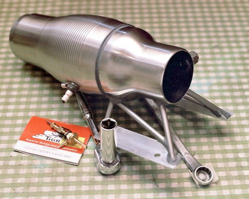
 The engine so far, along with the tools used in mounting the plug.
A six-point socket, as shown here, should be used around the plug
body, to prevent slipping off and breaking the porcelain insulator.
The tape can still be seen attached to the 12-point box-end wrench
used to reach inside the engine to hold the plug mount nut. Also
shown is the soon-to-be modified Super Tigre needle valve assembly,
which at $18.00 US turned out to be the most expensive single part
of the entire engine.
The engine so far, along with the tools used in mounting the plug.
A six-point socket, as shown here, should be used around the plug
body, to prevent slipping off and breaking the porcelain insulator.
The tape can still be seen attached to the 12-point box-end wrench
used to reach inside the engine to hold the plug mount nut. Also
shown is the soon-to-be modified Super Tigre needle valve assembly,
which at $18.00 US turned out to be the most expensive single part
of the entire engine.
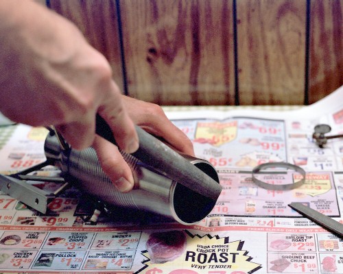
 The jeweler's saw turned out to be an easy way to remove the short,
cylindrical ring at the tail end of the engine. Once the cut was
started, it was worked all the way around, keeping fairly close to
the rolled zone [about 3/8 inch forward of the rim].
The jeweler's saw turned out to be an easy way to remove the short,
cylindrical ring at the tail end of the engine. Once the cut was
started, it was worked all the way around, keeping fairly close to
the rolled zone [about 3/8 inch forward of the rim].
 Finally, a decent shot of the jeweler's saw in action! Cutting off
the short machined inner end of the Super Tigre needle valve body:
Finally, a decent shot of the jeweler's saw in action! Cutting off
the short machined inner end of the Super Tigre needle valve body:
 VIII. Finishing up [03 October 2003]:
Previous section Next section Back to Contents Top of page Page 1 Page 3
Subscribe to jetZILLA Online Magazine (it's FREE!)
The parts of the fuel tube [liquid fuel version]: The main tube is
3/16-inch OD brass tubing, the shoulder tube is 1/4-inch tubing.
The tiny part to the left of the main needle valve body is the
small machined end that was being removed in the previous photo;
it will be discarded. The needle valve entrance pipe and main
valve body have been 'ported' out with a jeweler's drill to an
approximately .055 inch ID.
VIII. Finishing up [03 October 2003]:
Previous section Next section Back to Contents Top of page Page 1 Page 3
Subscribe to jetZILLA Online Magazine (it's FREE!)
The parts of the fuel tube [liquid fuel version]: The main tube is
3/16-inch OD brass tubing, the shoulder tube is 1/4-inch tubing.
The tiny part to the left of the main needle valve body is the
small machined end that was being removed in the previous photo;
it will be discarded. The needle valve entrance pipe and main
valve body have been 'ported' out with a jeweler's drill to an
approximately .055 inch ID.
![Parts for the second fuel tube [for liquid fuels], ready for final assembly (c) 2003 Larry Cottrill](http://www.cottrillcyclodyne.com/Maggie_Muggs/Fuel_pipe_parts_crop1.jpg) The fully finished fuel pipe for liquid fuels. The thin film of
J-B Weld at the left end of the shoulder pipe will be easily
cleaned up with a few strokes of fine sandpaper.
The fully finished fuel pipe for liquid fuels. The thin film of
J-B Weld at the left end of the shoulder pipe will be easily
cleaned up with a few strokes of fine sandpaper.
![The second fuel tube [for liquid fuels], fully assembled using J-B Weld (c) 2003 Larry Cottrill](http://www.cottrillcyclodyne.com/Maggie_Muggs/Fuel_pipe_finished_crop1.jpg) The fuel pipe going into the pipe mount. The bonnet nut is slid on,
followed by the properly-oriented slip ring and the collet. Then
the whole assembly is inserted into the mount and slid in until the
metering holes at the far end of the pipe are perfectly centered in
the intake opening.
The fuel pipe going into the pipe mount. The bonnet nut is slid on,
followed by the properly-oriented slip ring and the collet. Then
the whole assembly is inserted into the mount and slid in until the
metering holes at the far end of the pipe are perfectly centered in
the intake opening.
![Assembling the second [liquid fuel] fuel pipe into the pipe mount (c) 2003 Larry Cottrill](http://www.cottrillcyclodyne.com/Maggie_Muggs/Fuel_pipe_going_in_crop1.jpg) The new fuel pipe fully installed, just after tightening up with an
adjustable wrench. It is not necessary to tighten the nut
excessively; just enough to keep the pipe from rotating as the
needle valve is adjusted.
The new fuel pipe fully installed, just after tightening up with an
adjustable wrench. It is not necessary to tighten the nut
excessively; just enough to keep the pipe from rotating as the
needle valve is adjusted.
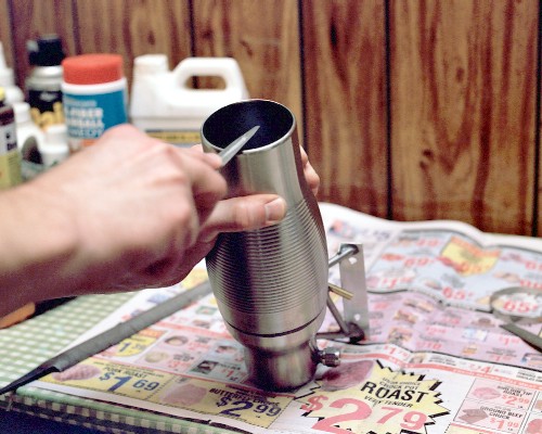
![The second fuel pipe [for liquid fuels], fully installed in the pipe mount (c) 2003 Larry Cottrill](http://www.cottrillcyclodyne.com/Maggie_Muggs/Fuel_pipe_installed_crop1.jpg) The cut end of the exhaust nozzle is smoothed up with a good-sized
half-round file ...
The cut end of the exhaust nozzle is smoothed up with a good-sized
half-round file ...
 ... and finished with a smaller one:
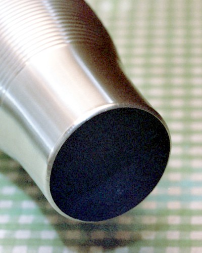
 The end result is a smooth opening with just enough 'rolled edge'
left intact to strengthen the rim:
The end result is a smooth opening with just enough 'rolled edge'
left intact to strengthen the rim:
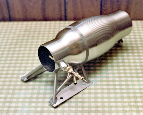
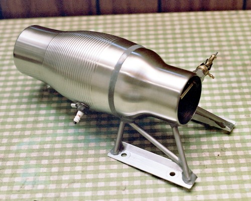
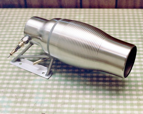
 Maggie Muggs, finished at last - finished weight 10.6 ounces [0.66 pound]:
 Previous section Next section Back to Contents Top of page Page 1 Page 3
Subscribe to jetZILLA Online Magazine (it's FREE!)
Previous section Next section Back to Contents Top of page Page 1 Page 3
Subscribe to jetZILLA Online Magazine (it's FREE!)
 All film processing and negative
scanning for this page was done by
Multi Media Imaging
1526 Walnut Street
Des Moines, Iowa USA 50309
515-309-3456
www.multi-media-inc.com
All film processing and negative
scanning for this page was done by
Multi Media Imaging
1526 Walnut Street
Des Moines, Iowa USA 50309
515-309-3456
www.multi-media-inc.com
|
|